


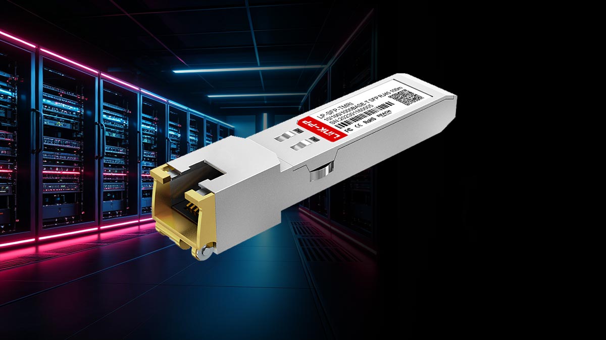
The 10/100/1000BASE-T SFP (also known as RJ45 Copper SFP or SFP-T module) has become a critical building block in modern Ethernet networking, especially in environments where flexibility, mixed infrastructure, and cost efficiency are required. It allows network engineers to convert an SFP port into a standard RJ45 Ethernet interface, supporting speeds from 10 Mbps to 1 Gbps over copper cabling.
Despite its widespread use, this module is often misunderstood. Many users assume it is a simple “adapter” between fiber SFP slots and RJ45 ports. In reality, a 1000BASE-T SFP is a fully integrated active transceiver that contains a dedicated Ethernet PHY chip responsible for signal processing, auto-negotiation, and electrical conversion. This internal complexity is what enables compatibility with standard Cat5e/Cat6 infrastructure—but it also introduces challenges such as higher power consumption, heat generation, and vendor compatibility limitations.
In real-world deployments, network engineers frequently encounter issues such as “unsupported transceiver” errors, unstable links, or overheating modules, particularly in high-density switches from vendors like Cisco, HP Aruba, and MikroTik. These problems are not caused by a failure of the SFP standard itself, but rather by differences in firmware validation rules, chipset design quality, and environmental conditions.
As network architectures continue to evolve toward higher-speed optical interfaces such as SFP28 and QSFP28, the role of copper SFP modules is also shifting. However, they remain highly relevant in edge networks, legacy system integration, and small-to-medium enterprise environments where RJ45 infrastructure is still dominant.
This article provides a complete breakdown of the 10/100/1000BASE-T SFP module, including how it works internally, why compatibility issues occur, how to troubleshoot common failures, and when it is the right or wrong choice for your network design. It is designed to help engineers, IT buyers, and system designers make informed decisions backed by real-world deployment insights and industry behavior patterns.
🔶 What Is a 10/100/1000BASE-T SFP Module?
A 10/100/1000BASE-T SFP module (also known as Copper SFP, RJ45 SFP, or SFP-T) is a hot-pluggable transceiver that enables RJ45 Ethernet connectivity through an SFP slot on switches, routers, or media devices. It allows fiber-only SFP ports to support standard twisted-pair copper cabling.
Unlike passive adapters, it is an active electronic device with full signal processing capability, making it significantly more complex than a simple interface converter.
Definition of Copper SFP (SFP-T)
A copper SFP (SFP-T) is an Ethernet transceiver that converts an SFP interface into an RJ45 port for communication over Cat5e/Cat6/Cat6a cables.
Key features:
Supports 10/100/1000 Mbps Ethernet
RJ45 connector interface
Works over standard twisted-pair copper cabling
Plug-and-play SFP compatibility
Typical reach up to 100 meters
It serves as a practical bridge between fiber-based switching hardware and legacy copper Ethernet networks, especially in mixed infrastructure environments.
Built-in PHY Chip (Core Technical Insight)
A defining feature of the 1000BASE-T SFP module is its internal Ethernet PHY (Physical Layer) chip, which handles all electrical signal processing.
Unlike fiber SFPs, which directly transmit optical signals, copper SFP modules perform:
Electrical signal encoding/decoding
Noise and echo cancellation
Clock recovery and synchronization
Auto-negotiation with the link partner
Conversion between SFP interface and RJ45 signaling
This effectively makes the module a miniature Ethernet NIC inside an SFP form factor.
As a result, copper SFP modules:
Consume more power than fiber SFPs
Generate higher operating temperatures
Require more complex circuitry
Are more sensitive to firmware and compatibility rules
Why It Supports 10/100/1000 Mbps Auto-Negotiation
The 10/100/1000BASE-T SFP module supports multi-speed operation through IEEE 802.3 auto-negotiation, enabled by its internal PHY chipset.
How it works:
Detects link partner capabilities
Exchanges speed and duplex parameters
Negotiates the highest common supported rate
Establishes the connection automatically
Supported speeds:
10 Mbps (Ethernet)
100 Mbps (Fast Ethernet)
1000 Mbps (Gigabit Ethernet)
Why it matters:
Ensures backward compatibility
Adapts to cable quality conditions
Reduces manual configuration
Supports mixed network environments
In practice, however, issues may still occur due to:
Cable quality limitations
Vendor firmware restrictions
Duplex mismatches
Low-quality PHY implementations
Therefore, stable performance depends not only on the standard itself, but also on module design quality and system compatibility testing.
🔶 How 1000BASE-T SFP Technology Works Inside
The 1000BASE-T SFP (RJ45 Copper SFP) module is not a simple electrical adapter. Internally, it is a highly integrated active device that performs real-time signal processing to enable Gigabit Ethernet transmission over standard copper cabling. Its operation relies on a compact but powerful architecture centered around an Ethernet PHY chipset.
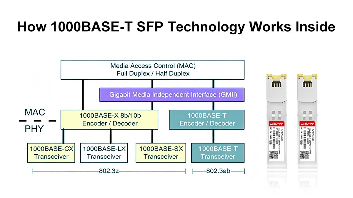
Internal Ethernet PHY Conversion Process
At the core of a 1000BASE-T SFP module is the Ethernet PHY (Physical Layer) chip, which acts as the main processing engine.
The internal workflow typically includes:
Receiving data from the SFP host interface
Converting digital signals into Ethernet PHY format
Encoding signals for copper transmission
Managing full-duplex bidirectional communication over four twisted pairs
Handling auto-negotiation and link synchronization
This PHY-based processing allows the module to operate as a self-contained Ethernet interface inside an SFP cage, rather than a passive converter.
Electrical Signal vs. Optical Signal Transformation
The key difference between copper SFP and fiber SFP lies in the type of signal conversion process:
RJ45 Copper SFP (Electrical Transmission)
Uses electrical voltage signals over twisted-pair copper
Requires signal equalization and noise compensation
Supports bidirectional communication on all four wire pairs
Heavily dependent on PHY-level processing
Fiber SFP (Optical Transmission)
Converts electrical signals into light via laser diode
Transmits data through fiber optic cable
Uses photodiode for light-to-electrical conversion
Simpler signal path with lower processing overhead
Because copper transmission is more susceptible to interference, the module must actively correct signal distortion in real time, increasing processing complexity.
Power Consumption and Heat Generation Mechanism
One of the most important engineering characteristics of 1000BASE-T SFP modules is their relatively high power consumption.
Why power usage is higher:
Continuous PHY signal processing
DSP (digital signal processing) operations for noise cancellation
Echo suppression and adaptive equalization
Multi-speed auto-negotiation logic (10/100/1000 Mbps)
Resulting effects:
Higher electrical load per module (typically 1W–2.5W+)
Significant heat generation in compact SFP form factor
Increased switch chassis temperature in high-density deployments
This is why copper SFP modules are often avoided in tightly packed data center environments where thermal efficiency is critical.
Why Copper SFP Is More Complex Than Fiber SFP
Although both modules share the same SFP form factor, the internal engineering complexity is fundamentally different.
1. Signal Processing Complexity
Copper SFP: Requires full PHY + DSP processing
Fiber SFP: Primarily optical conversion with simpler logic
2. Error Correction Requirements
Copper: Must actively correct noise, interference, and attenuation
Fiber: Naturally immune to electromagnetic interference
3. Hardware Architecture
Copper SFP: Includes RJ45 controller, PHY chip, and analog processing circuits
Fiber SFP: Laser driver + photodiode + control IC
4. Environmental Sensitivity
Copper SFP: Sensitive to cable quality, EMI, and heat
Fiber SFP: Stable across long distances and harsh environments
From a practical deployment perspective, the complexity of 1000BASE-T SFP modules explains three common real-world behaviors observed by network engineers:
Higher failure rates in poor ventilation environments
Compatibility sensitivity across different switch vendors
Performance variation depending on cable quality and length
These characteristics are not design flaws, but inherent consequences of performing full Ethernet PHY processing inside a compact SFP module.
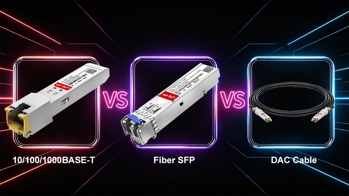
🔶 10/100/1000BASE-T SFP vs. Fiber SFP vs. DAC Cable
When designing modern Ethernet networks, engineers often choose between copper SFP (RJ45 1000BASE-T), fiber SFP modules, and DAC (Direct Attach Copper) cables. Although all three solutions serve short- to medium-distance connectivity, they differ significantly in latency, power consumption, deployment flexibility, and long-term scalability.
Understanding these differences is critical for selecting the right interconnect solution in enterprise and data center environments.
Type | Power | Heat | Distance | Use Case |
|---|---|---|---|---|
Copper SFP | High | High | ~100m | Legacy RJ45 integration |
Fiber SFP | Low | Low | Long range | Core networks |
DAC | Very low | Low | 1–10m | Data centers |
Latency Comparison
Latency varies depending on the transmission method and internal processing requirements.
Copper SFP (10/100/1000BASE-T)
Highest latency among the three options
Requires internal PHY signal processing and DSP operations
Additional delay introduced by electrical signal conditioning
Fiber SFP
Very low latency
Direct optical signal transmission with minimal processing
Ideal for high-speed backbone and aggregation layers
DAC Cable
Lowest latency in practical deployments
Passive or minimally active copper transmission
Direct electrical connection between devices
Summary: DAC < Fiber SFP < Copper SFP (in latency performance)
Power Consumption Differences
Power efficiency is a key factor in high-density networking environments.
Copper SFP
Highest power consumption (typically ~1W–2.5W+)
Requires continuous PHY processing
Generates noticeable heat inside switches
Fiber SFP
Moderate power consumption (~0.5W–1W depending on optics)
Efficient optical conversion with lower DSP overhead
DAC Cable
Lowest power usage (especially passive DAC)
Minimal or no active signal processing required
Summary: DAC (best efficiency) → Fiber SFP → Copper SFP (highest consumption)
Distance and Deployment Scenarios
Each solution is optimized for different network distances and environments.
Copper SFP (RJ45)
Up to ~100 meters
Best for edge connectivity and legacy Ethernet devices
Common in office LANs and mixed infrastructure environments
Fiber SFP
From 550m (multimode) to 10km–80km+ (single-mode)
Ideal for data center backbone, campus networks, and WAN links
Supports high-speed scalability (1G–400G ecosystems)
DAC Cable
Typically 0.5m–10m
Best for rack-to-rack connections in data centers
Common between switches, servers, and storage systems
Cost vs. Performance Trade-offs
Choosing the right solution often depends on balancing cost, performance, and operational complexity.
Copper SFP
Low initial deployment cost (uses existing RJ45 infrastructure)
Higher long-term operational cost due to power and heat
Limited scalability for high-density environments
Fiber SFP
Higher initial cost (optics + fiber cabling)
Excellent long-term scalability and stability
Lower failure rates and better energy efficiency
DAC Cable
Lowest total cost for short-range connections
Extremely cost-effective in data centers
Limited flexibility due to fixed cable lengths
Key insight: Copper SFP is cost-effective for compatibility, not for performance scaling.
When NOT to Use Copper SFP
Despite its flexibility, the 10/100/1000BASE-T SFP module is not suitable for all environments.
You should avoid copper SFP in the following scenarios:
❌ High-density data center environments
Excessive heat accumulation
Increased switch cooling load
Reduced long-term reliability
❌ High-performance or low-latency networks
Adds additional PHY processing delay
Not suitable for latency-sensitive applications
❌ Long-term backbone infrastructure
Limited to 100m distance
Not scalable for modern high-speed architectures
❌ Poor airflow or thermal-constrained switches
Copper SFP modules increase internal temperature significantly
May affect adjacent ports and overall system stability
🔶 Best Use Cases for Copper SFP Modules
Although 10/100/1000BASE-T SFP (RJ45 Copper SFP) modules are not ideal for every network scenario, they remain highly valuable in specific deployment environments where flexibility, backward compatibility, and cost efficiency are more important than maximum performance or energy efficiency.
Below are the most practical and widely adopted use cases based on real-world networking deployments.
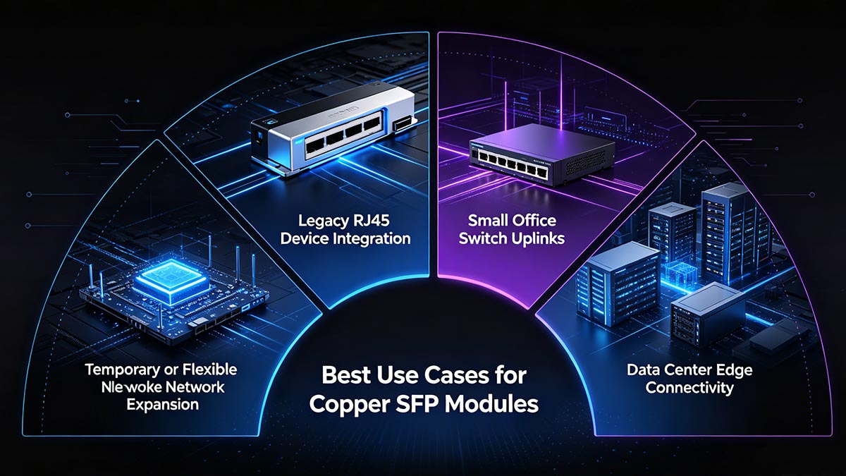
1. Legacy RJ45 Device Integration
One of the most common applications of copper SFP modules is connecting legacy RJ45-based devices to modern SFP-only switches.
Typical scenarios include:
Older servers without fiber interfaces
IP cameras in surveillance systems
Industrial controllers and PLC devices
Legacy routers or access points
In these environments, replacing existing infrastructure with fiber-ready hardware is often costly or impractical. A copper SFP provides a simple and cost-effective bridge between modern switch architecture and legacy Ethernet devices.
2. Small Office Switch Uplinks
In small and medium-sized business (SMB) networks, copper SFP modules are frequently used for uplinking switches to routers or distribution devices.
Why it works well in SMB environments:
Existing structured RJ45 cabling is already deployed
Limited network distance requirements (<100 meters)
Lower traffic density compared to data centers
Cost-sensitive deployment model
This allows IT administrators to expand network capacity without redesigning the physical cabling infrastructure.
3. Temporary or Flexible Network Expansion
Copper SFP modules are also widely used in temporary network expansion scenarios, such as:
Event or exhibition networks
Short-term office setups
Disaster recovery or emergency network restoration
Pilot testing environments
Key advantages:
Plug-and-play deployment
No need for fiber termination or splicing
Works with existing copper patch cables
Easily removable and reusable
4. Data Center Edge Connectivity (Limited Use Cases)
In modern data centers, copper SFP modules are generally not preferred for core switching, but they still have limited use at the edge layer.
Suitable edge applications:
Management network access ports
Low-bandwidth monitoring systems
Temporary connection points for testing equipment
Interfacing with external RJ45-based devices
However, their usage in data centers is constrained due to:
Higher heat output
Increased power consumption
Limited scalability in high-density environments
Preference for fiber SFP and DAC solutions
🔶 Common Problems with RJ45 Copper SFP Modules
While 10/100/1000BASE-T SFP (RJ45 Copper SFP) modules are widely used for their flexibility, they also introduce several operational challenges in real-world deployments. These issues are primarily related to heat, signal integrity, compatibility, and power constraints, especially in enterprise and mixed-vendor networks.
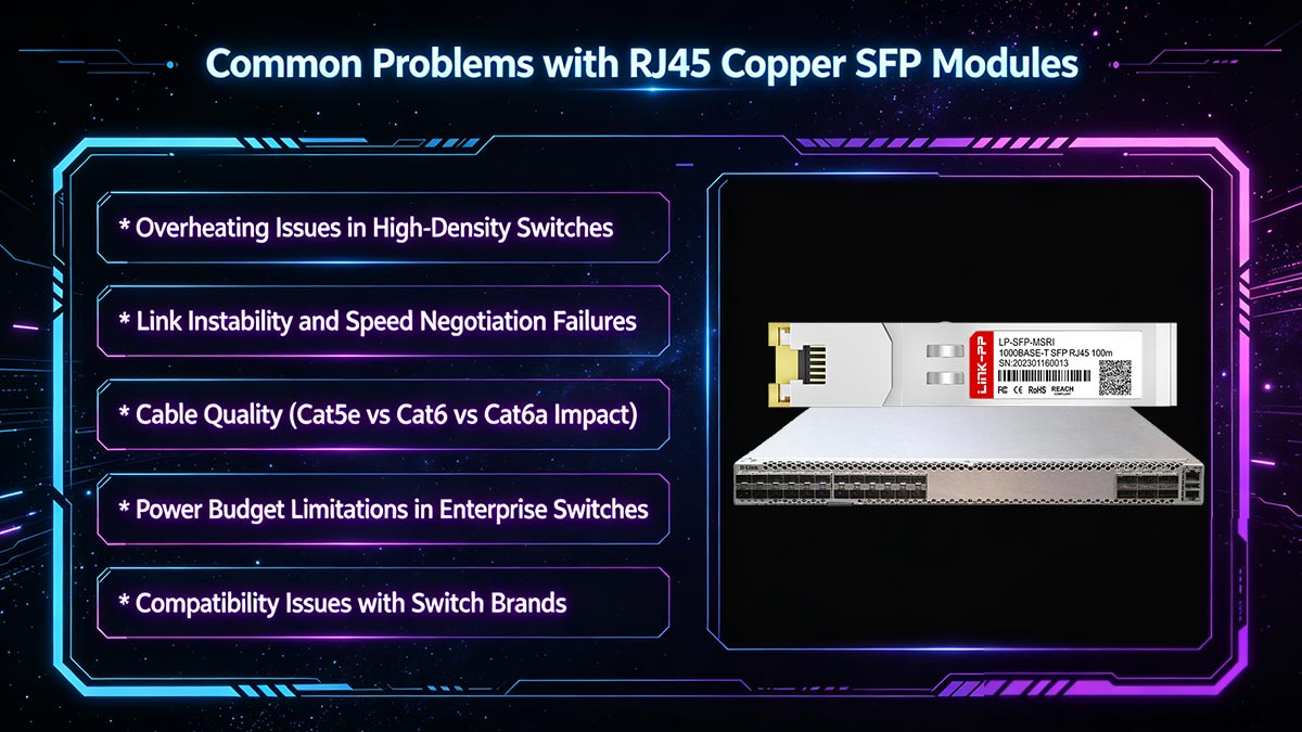
▶ Overheating Issues in High-Density Switches
Copper SFP modules generate significantly more heat than fiber transceivers because they contain a full Ethernet PHY chipset inside a compact SFP form factor.
Common symptoms:
Switch fans running at higher speed
Elevated chassis temperature
Heat accumulation near adjacent ports
Reduced long-term module stability
Root cause:
Continuous DSP processing and electrical signal conversion within a confined space increases thermal load, especially when multiple RJ45 SFPs are installed in high-density switches.
▶ Link Instability and Speed Negotiation Failures
Another frequent issue is unstable link behavior or incorrect speed negotiation.
Typical problems:
Link flapping (up/down cycles)
Connection stuck at 100 Mbps instead of 1 Gbps
No link detection under normal conditions
Main causes:
Auto-negotiation mismatch between devices
Firmware behavior differences across switch vendors
PHY chipset quality variations
Cable performance limitations under load
▶ Cable Quality (Cat5e vs Cat6 vs Cat6a Impact)
The performance of a 1000BASE-T SFP module is highly dependent on copper cabling quality.
Industry guidelines:
Cat5e: Minimum requirement for 1 Gbps up to 100m
Cat6: Recommended for stable Gigabit performance
Cat6a: Best for reduced interference and higher reliability
Common failure scenarios:
Poor-quality or damaged cables causing packet loss
Long cable runs reducing effective speed
EMI interference in industrial environments
In practice, many “SFP failures” are actually cabling issues rather than module defects.
▶ Power Budget Limitations in Enterprise Switches
Copper SFP modules consume more power than fiber SFPs, which can create constraints in high-density deployments.
Key issues:
Limited per-port SFP power allocation
Reduced number of supported copper SFPs per switch
Increased overall switch power and cooling demand
Impact: In large deployments, excessive copper SFP usage may require thermal and power planning adjustments to maintain system stability.
▶ Compatibility Issues with Switch Brands (Cisco, HP, MikroTik)
One of the most critical challenges with RJ45 SFP modules is vendor compatibility restrictions.
Vendor-coded optics / EEPROM locking
Many switch manufacturers implement EEPROM-based identification systems that validate whether a transceiver is officially approved.
Each SFP module contains vendor ID data
Switch firmware checks compatibility before enabling the port
Non-approved modules may be rejected or disabled
“Unsupported transceiver” error explanation
A common issue—especially on Cisco platforms—is the message:
“Unsupported transceiver”
This occurs when:
The module is not recognized in the switch’s compatibility database
EEPROM coding does not match vendor requirements
Firmware restrictions block third-party optics
Real-world compatibility matrix considerations
In practice, compatibility depends on multiple factors:
Switch model and hardware revision
Firmware version
Module chipset and coding type
Vendor-specific whitelist policies
This creates a complex compatibility matrix where a module may work on one device but fail on another, even within the same brand.
Why not all RJ45 SFP modules are interchangeable
Although physically identical, copper SFP modules are not universally interchangeable due to:
Different PHY chipset implementations
Vendor-specific EEPROM programming
Variations in power and thermal design
Firmware-level validation rules
As a result, enterprise deployments often require pre-tested or vendor-coded RJ45 SFP modules to ensure stable operation across mixed network environments.
🔶 Troubleshooting Guide for 1000BASE-T SFP Issues
In real-world deployments, 10/100/1000BASE-T SFP (RJ45 Copper SFP) modules may experience compatibility, link, or performance issues that are typically related to configuration, cabling, or hardware constraints rather than complete module failure. The following troubleshooting guide covers the most common problems and proven resolution methods.
SFP Not Detected or “Unsupported Transceiver” Error Fix
This is one of the most frequently reported issues, especially in Cisco, HP Aruba, and MikroTik environments.
Common causes:
Vendor-coded EEPROM mismatch
Switch firmware blocking third-party optics
Incompatible module chipset
Outdated switch software version
Recommended solutions:
Verify switch compatibility matrix before installation
Update switch firmware to the latest stable version
Use vendor-coded or multi-vendor compatible SFP modules
Re-seat the module and reboot the switch if necessary
In many cases, the issue is not physical failure but firmware-level validation restriction.
Link Down or Unstable Connection Solutions
A link that fails to establish or frequently drops is usually related to physical layer or negotiation issues.
Common causes:
Poor or damaged Ethernet cable
Incorrect cable category (below Cat5e)
Auto-negotiation mismatch
EMI interference in industrial environments
Recommended solutions:
Replace cable with Cat5e or Cat6 certified patch cord
Ensure both devices are set to auto-negotiation mode
Test with a known-good switch port
Reduce cable length if close to 100m limit
Avoid routing near high electromagnetic interference sources
Speed Stuck at 100 Mbps Causes
A common performance issue is the module negotiating at 100 Mbps instead of 1 Gbps, even when Gigabit is expected.
Possible causes:
Cable quality limitation or internal wiring faults
Poor RJ45 termination or damaged connectors
Auto-negotiation fallback due to signal degradation
Switch or endpoint forced to Fast Ethernet mode
Recommended solutions:
Replace with Cat6 or higher-grade cable
Verify both ends support 1000BASE-T full duplex
Check port configuration for forced speed settings
Test module in a different switch port to isolate the issue
In most cases, this issue is cable-related rather than SFP-related.
Cooling and Ventilation Recommendations
Because copper SFP modules generate more heat than fiber optics, thermal management is critical for stable operation.
Best practices:
Avoid installing multiple RJ45 SFP modules adjacent to each other
Ensure proper airflow within switch chassis
Maintain clean and unobstructed ventilation paths
Use switches with active cooling for high-density deployments
Monitor switch temperature in enterprise environments
Engineering insight:
Each 1000BASE-T SFP module contains an active PHY chip that continuously processes Ethernet signals, resulting in higher power dissipation and localized heat buildup.
Most 1000BASE-T SFP issues are not caused by module failure, but instead result from:
Compatibility restrictions (vendor locking)
Cable quality limitations
Thermal constraints in high-density environments
Auto-negotiation mismatches
Proper deployment planning and high-quality module selection are essential for achieving stable long-term performance in enterprise networks.
🔶 How to Choose a Reliable 10/100/1000BASE-T SFP
Selecting a high-quality 10/100/1000BASE-T SFP (RJ45 Copper SFP) module is critical for ensuring stable performance, long-term reliability, and compatibility across different network environments. Unlike fiber SFPs, copper SFPs integrate a full PHY chipset and are more sensitive to design quality, thermal performance, and vendor compatibility.
1. Importance of Chipset Quality
The internal Ethernet PHY chipset is the core of a copper SFP module and directly determines performance stability.
Why chipset quality matters:
Controls signal encoding and decoding accuracy
Impacts auto-negotiation stability (10/100/1000 Mbps)
Affects latency and packet reliability
Influences power consumption and heat output
High-quality chipset benefits:
More stable link performance under load
Better compatibility with different switch brands
Reduced packet loss in noisy environments
Lower failure rate in long-term operation
In enterprise deployments, chipset quality is often the primary factor separating stable modules from unstable ones.
2. Compatibility Testing Before Deployment
Because many switches enforce strict transceiver validation, pre-deployment testing is essential.
Key testing steps:
Verify module recognition on target switch model
Test link stability under real traffic load
Confirm auto-negotiation at 1 Gbps
Check behavior across multiple switch ports
Why it matters:
Avoids “unsupported transceiver” issues
Prevents unexpected network downtime
Ensures consistent behavior across environments
A module that works on one switch may not behave the same on another, even within the same brand.
3. Thermal Design Considerations
Copper SFP modules generate more heat than fiber modules due to internal PHY processing.
Important thermal factors:
Power consumption (typically 1W–2.5W+)
Heat dissipation efficiency of module housing
Airflow conditions inside switch chassis
Best practices:
Use modules with optimized thermal design
Avoid dense placement of RJ45 SFPs
Ensure adequate switch ventilation
Monitor temperature in production environments
Poor thermal design can lead to instability, reduced lifespan, or intermittent link failures.
4. OEM vs. Third-Party Modules
Choosing between OEM and third-party SFP modules depends on budget, compatibility needs, and deployment scale.
OEM modules:
Guaranteed compatibility with vendor switches
Higher cost
Typically supported by switch manufacturer warranties
Third-party modules:
More cost-effective
Available with multi-vendor compatibility options
May require coding or compatibility verification
In modern deployments, many enterprises use tested third-party modules with proper compatibility validation to balance cost and flexibility.
5. Vendor Coding Support Importance
One of the most critical factors in real-world deployment is EEPROM coding compatibility.
Why it matters:
Switches read module identity from EEPROM
Incorrect coding can trigger “unsupported transceiver” errors
Vendor-specific firmware may block non-approved modules
Key considerations:
Cisco, HP Aruba, and other vendors often require specific coding
Multi-vendor coded modules improve deployment flexibility
Proper coding ensures plug-and-play behavior across platforms
Vendor coding support is essential for avoiding compatibility issues in heterogeneous network environments.
Engineering Insight
From an engineering perspective, reliable 1000BASE-T SFP performance depends on a combination of chipset quality, thermal design, and validated compatibility—not just physical form factor compliance.
In enterprise environments, the most successful deployments typically use modules that are:
Professionally tested under load conditions
Verified across multiple switch platforms
Designed with stable PHY and thermal architecture
Supported by accurate vendor or multi-vendor coding
🔶 Conclusion: Is 10/100/1000BASE-T SFP Right for You?
The 10/100/1000BASE-T SFP (RJ45 Copper SFP) remains a practical and widely used networking solution, but it is not a universal replacement for fiber SFP or DAC technologies. Its value lies in flexibility and compatibility, not maximum performance or energy efficiency.
To determine whether it is the right choice for your network, you should evaluate your requirements based on deployment scale, performance expectations, and infrastructure constraints.
Summary Decision Framework
Use the following simple framework to guide your decision:
Choose 10/100/1000BASE-T SFP if:
You need to connect RJ45-based legacy devices
Your network is within short distance limits (≤100 meters)
You are working in small office or edge environments
You require fast deployment without re-cabling infrastructure
Avoid copper SFP if:
You are building a high-density data center
Your application is latency-sensitive or performance-critical
You require long-term scalable backbone architecture
Your switch environment has strict thermal limitations
Final Engineering Insight
From a real-world network design perspective, 10/100/1000BASE-T SFP modules should be treated as a compatibility tool rather than a core infrastructure component.
They are most effective when used strategically at the network edge or in transitional environments—not as the foundation of high-performance architectures.
Reliable Copper SFP Solutions
If your project requires stable and compatible RJ45 SFP solutions, selecting high-quality modules with tested chipset design and multi-vendor compatibility is essential for long-term network reliability.
👉 Explore professional-grade optical transceivers and connectivity solutions at the LINK-PP Official Store, designed to support enterprise networking environments with consistent performance and compatibility assurance.


