

In today’s high-speed networking environments, the SFP Standard (Small Form-factor Pluggable) plays a critical role in enabling flexible and scalable fiber and copper connectivity across switches, routers, and network interface devices. From enterprise data centers to telecom infrastructure and industrial Ethernet systems, SFP modules have become a foundational component for building reliable, high-performance networks.
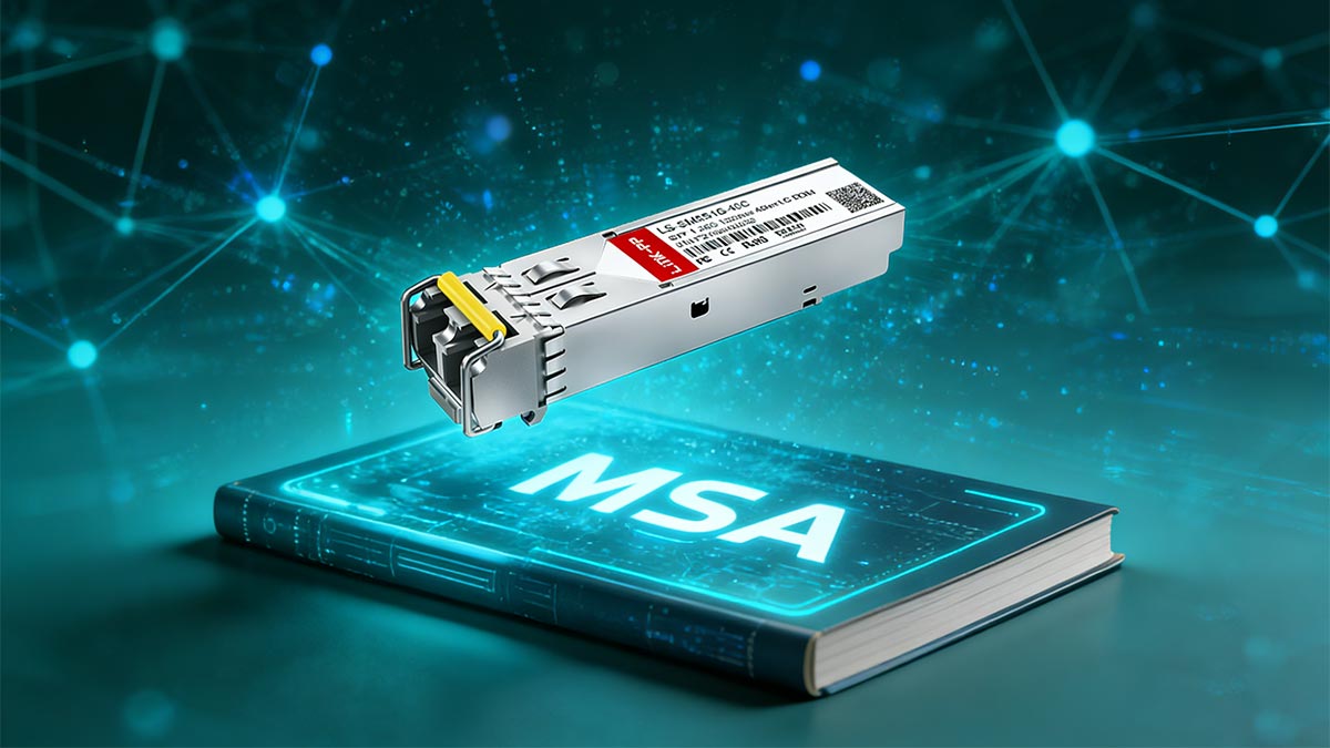
However, despite its widespread adoption, the term “SFP standard” is often misunderstood. Many users assume it refers to a fully universal, plug-and-play networking standard similar to USB. In reality, SFP is defined by a Multi-Source Agreement (MSA) rather than a strict IEEE interoperability standard. This means that while all SFP modules share a common physical form factor and basic electrical interface, their real-world compatibility can vary significantly depending on factors such as data rate, wavelength, fiber type, and vendor-specific firmware restrictions.
This gap between “standardized design” and “practical compatibility” is one of the most common causes of confusion—and network deployment issues—reported by engineers and IT professionals. In fact, many real-world discussions highlight situations where SFP modules physically fit into a port but fail to function due to hidden compatibility constraints or vendor lock-in policies.
In this article, we will break down the SFP Standard from both a technical and practical perspective, helping you understand:
What the SFP standard actually
defines (and what it does not)
Why compatibility is not guaranteed even under the same “standard”
How SFP modules behave in real-world network environments
And how to choose the right module to avoid costly deployment mistakes
By the end of this guide, you will have a clear, engineering-level und
erstanding of the SFP ecosystem—allowing you to make more informed decisions when selecting or deploying SFP modules in modern 1G and 10G+ networks.
🟡 What Is the SFP Standard? (Definition + MSA Explained)
The SFP Standard refers to a widely adopted networking interface design used for connecting switches, routers, and other networking equipment through fiber or copper links. Although it is commonly described as a “standard,” SFP is not a single rigid IEEE specification. Instead, it is built around a set of industry-defined agreements that ensure basic interoperability at the physical and electrical level while still allowing vendor flexibility.
To fully understand the SFP standard, it is important to break it down into four key aspects: its definition, the role of the Multi-Source Agreement (MSA), why it is not a strict IEEE standard, and what “standard” really means in practical networking environments.
1. Definition of Small Form-factor Pluggable (SFP)
Small Form-factor Pluggable (SFP) is a compact, hot-swappable transceiver module used in networking equipment to transmit and receive data over optical fiber or copper cables.
Key characteristics include:
Hot-swappable design: Modules can be inserted or removed without powering down devices
Modular architecture: One port supports multiple media types (fiber or copper)
Scalable speeds: Commonly used for 1G Ethernet, with extended variants supporting higher rates
Dual-function operation: Handles both transmission (TX) and reception (RX) of data signals
In practical networking terms, SFP enables a single switch or router port to support multiple physical media types simply by changing the transceiver module.
2. Role of Multi-Source Agreement (MSA)
The SFP ecosystem is governed primarily by a Multi-Source Agreement (MSA) rather than a single controlling standards body.
The MSA defines:
Mechanical dimensions (ensuring modules physically fit into any compliant SFP cage)
Electrical interface specifications (pin layout and signaling behavior)
Basic communication protocols between module and host device
Digital diagnostics framework (commonly based on SFF-8472)
The purpose of the MSA is to ensure that different manufacturers can produce interchangeable modules that physically and electrically fit into the same port design.
However, the MSA does not fully define:
Vendor authentication rules
Firmware-level compatibility checks
Performance tuning or extended features beyond the base specification
This is where real-world compatibility differences begin to appear.
3. Why SFP Is Not an IEEE “Strict” Standard
Unlike Ethernet standards such as IEEE 802.3, the SFP standard itself is not fully defined by IEEE as a complete end-to-end interoperability framework.
Instead:
IEEE defines Ethernet signaling standards (e.g., 1G, 10G, 25G)
The SFP MSA defines the physical module interface
Vendors implement additional proprietary logic on top of the base design
This separation creates a key distinction:
IEEE defines how data moves; SFP defines how the hardware module connects.
Because of this structure, two SFP modules can both comply with the MSA yet still behave differently depending on the host device and vendor ecosystem.
4. What “Standard” Actually Means in Networking
In networking terminology, the word “standard” does not always mean full universal compatibility. In the case of SFP, it should be understood as:
A shared physical design framework (form factor consistency)
A baseline electrical and signaling agreement
A minimum interoperability baseline, not a guarantee
This means:
All SFP modules will physically fit into any SFP-compliant port
Most will follow basic electrical rules defined by the MSA
But actual operational compatibility depends on additional factors, such as:
Device firmware restrictions
Vendor compatibility tables
Speed and protocol matching
Optical characteristics (wavelength, fiber type, distance class)
In other words, the SFP standard ensures structural compatibility, but not always functional compatibility.
While the SFP standard provides a unified foundation for modular networking hardware, its real-world behavior depends heavily on its technical specifications. In the next section, we will break down exactly what the SFP standard defines in practice—and what critical elements are often misunderstood or overlooked.
🟡 SFP Specifications Breakdown (What the Standard Defines)
While the term “SFP Standard” is often misunderstood as a guarantee of universal compatibility, the actual value of the standard lies in the precise technical specifications defined under the Multi-Source Agreement (MSA). These specifications ensure that SFP transceivers from different manufacturers can physically fit, electrically connect, and communicate at a basic level within compliant networking devices.
This section breaks down the core technical elements that are truly defined by the SFP standard.
1. Physical Form Factor and Hot-Swappable Design
One of the most important contributions of the SFP standard is its compact, modular physical design, which allows high-density networking equipment to scale efficiently.
Key physical characteristics include:
Standardized module size: Ensures consistent fit across all SFP cages
Hot-swappable capability: Modules can be inserted or removed without powering down the device
Locking mechanism: Provides secure mechanical retention during operation
Port density advantage: Enables multiple SFP ports on a single switch or router panel
The hot-swappable design is especially important in enterprise and telecom environments, where downtime must be minimized or eliminated during maintenance or upgrades.
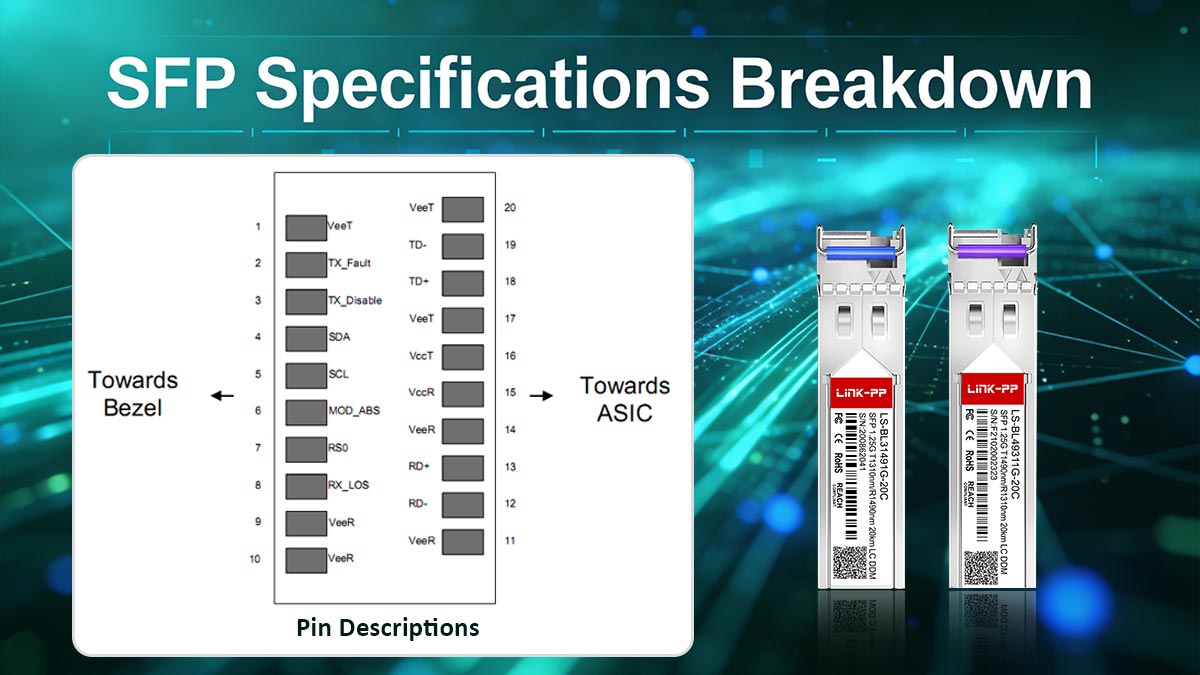
2. Electrical Interface and Pinout
The SFP standard defines a common electrical interface and pin configuration, which ensures that the module can communicate with host devices regardless of manufacturer.
Key aspects include:
Standardized pin layout (20-pin interface)
Low-voltage differential signaling (LVDS) support
Bidirectional data paths (TX and RX channels)
Management interface (I²C bus for communication with host system)
This standardized pinout ensures that SFP modules can transmit and receive data consistently, while also allowing the host device to query module status and configuration data.
However, while the electrical interface is standardized, how each device interprets or validates module data may still vary by vendor, which contributes to compatibility differences in real deployments.
3. Supported Data Rates (Fast Ethernet to Gigabit)
The SFP standard was originally designed to support 1G Ethernet applications, but it has evolved to accommodate a range of data rates depending on the specific implementation.
Common supported speeds include:
100 Mbps (Fast Ethernet in some legacy implementations)
1 Gbps (Gigabit Ethernet – primary SFP use case)
Fibre Channel variants (1G / 2G / 4G in storage networks)
It is important to note:
The SFP standard itself defines the form factor, not the speed evolution beyond its original scope.
Higher-speed technologies such as SFP+ (10G) and SFP28 (25G) extend the same physical concept but are governed by separate MSAs and stricter electrical requirements.
This means that a physically identical module does not guarantee identical performance capability.
4. Digital Diagnostics Monitoring (SFF-8472 / DOM)
A key enhancement within the SFP ecosystem is Digital Optical Monitoring (DOM), defined under SFF-8472 specifications.
DOM allows real-time monitoring of module health and performance, including:
Optical transmit power (TX power)
Optical receive power (RX power)
Temperature of the module
Supply voltage
Laser bias current
These parameters are accessible through the host device and are critical for:
Predictive maintenance
Network troubleshooting
Performance optimization
Preventing unexpected link failures
DOM has become an essential feature in modern networks, especially in data centers and telecom infrastructure, where visibility into optical performance directly impacts reliability.
📊 SFP Specifications Overview Table
Category | Specification | Description | Notes |
|---|---|---|---|
SFP (MSA-defined) | Compact hot-swappable module design | Fits all standard SFP cages | |
Interface | 20-pin electrical connector | Standardized host-module communication | Includes power, data, and control pins |
Data Rates | 100 Mbps – 1 Gbps | Supports Fast Ethernet & Gigabit Ethernet | Extended via related standards |
Protocol Support | Ethernet, Fibre Channel | Multi-protocol compatibility | Depends on module type |
Diagnostic Monitoring | SFF-8472 (DOM) | Real-time optical performance monitoring | TX/RX power, temperature, voltage |
Management Interface | I²C bus | Communication between host and module | Enables EEPROM reading |
Hot-Swappable | Yes | Modules can be replaced without shutdown | Critical for live networks |
Media Types | Fiber / Copper (RJ45 SFP) | Supports multiple transmission media | Depends on transceiver type |
Although the SFP standard clearly defines physical structure, electrical connectivity, and diagnostic capabilities, it does not fully eliminate real-world compatibility challenges. In the next section, we will explore why standard SFP modules are often not universally compatible across all vendors and devices, and what factors actually determine whether a module will work in practice.
🟡 SFP Compatibility Explained (Why “Standard” ≠ Universal)
Although the SFP Standard defines a unified physical form factor and basic electrical interface, it does not guarantee universal interoperability across all vendors and devices. This is one of the most misunderstood aspects in networking, and also one of the most common causes of deployment issues reported by engineers.
In practice, SFP compatibility is determined by a combination of hardware design, firmware validation, and optical parameters, rather than the “standard” alone. This is why two modules that look identical can behave very differently when installed in different switches or routers.
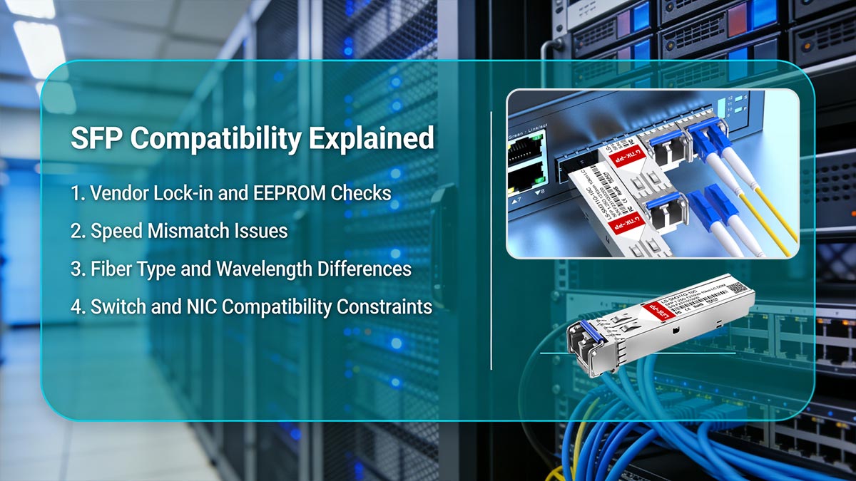
Below are the key reasons why “standard” does not equal “universally compatible.”
1. Vendor Lock-in and EEPROM Checks
Many network equipment vendors implement proprietary compatibility control mechanisms within their devices.
When an SFP module is inserted, the switch or router reads the module’s EEPROM data, which includes:
Vendor ID
Part number
Serial number
Compliance information
Some devices will:
✅ Accept only approved vendor IDs (whitelisting)
❌ Reject third-party modules (blacklisting or mismatch detection)
⚠️ Allow operation but show warnings or limited support
This creates a form of ecosystem lock-in, where physically compatible modules may still be blocked at the firmware level.
2. Speed Mismatch Issues
Another major compatibility factor is data rate alignment between module and port.
Common issues include:
1G SFP inserted into a 10G-only SFP+ port (may fail or downshift depending on device)
10G SFP+ module used in 1G-only ports (typically incompatible)
Auto-negotiation limitations in optical interfaces
Even though SFP and SFP+ share similar physical designs, their electrical signaling and encoding requirements differ significantly, which prevents seamless interchange in many cases.
3. Fiber Type (SMF vs. MMF) and Wavelength Differences
Optical compatibility depends heavily on the physical transmission medium and wavelength alignment.
Key mismatches include:
850nm (short-range) vs 1310nm / 1550nm (long-range) wavelengths
Mismatched optics between paired ends
If the transmitter and receiver are not matched correctly:
Signal attenuation increases
Link stability becomes unreliable
Connection may fail completely
This is one of the most common real-world SFP deployment errors.
4. Switch and NIC Compatibility Constraints
Even when physical and optical parameters are correct, host device compatibility rules can still block operation.
Common constraints include:
Vendor-specific firmware restrictions
Approved transceiver compatibility lists
Port speed limitations or auto-detection issues
Hardware-level validation checks
Enterprise-grade switches often maintain strict compatibility matrices, meaning only tested or certified modules are guaranteed to work without warnings or errors.
📌 Four Key Compatibility Factors
SFP compatibility is not defined by the “standard” alone, but by four critical factors:
Vendor Validation (EEPROM & firmware checks)
Determines whether the device accepts the module.Speed Matching (1G / 10G / 25G alignment)
Ensures electrical and protocol compatibility.Optical Parameters (Fiber type & wavelength)
Must match on both ends of the link.Device Compatibility (Switch/NIC support rules)
Controlled by vendor-specific hardware and software policies.
Understanding these compatibility constraints is essential because they explain why many “standard SFP modules” fail in real-world deployments. Next, we will compare SFP vs. SFP+ vs. SFP28, and explain how these generations evolved while maintaining partial—but not complete—interoperability.
🟡 SFP vs. SFP+ vs. SFP28 — Key Differences and Interoperability
The SFP ecosystem has evolved through multiple generations to support increasing network speeds, from 1G Ethernet (SFP) to 10G (SFP+) and now 25G (SFP28). While these modules share a similar physical form factor, they are built on different electrical and protocol specifications, which directly impacts compatibility and upgrade decisions.
Understanding the differences between these three standards is essential for avoiding mismatches in modern data center and enterprise networks.
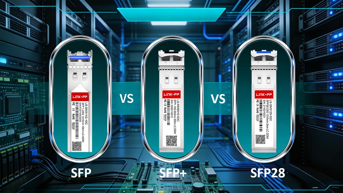
1. 1G vs. 10G vs. 25G Comparison (SFP vs. SFP+ vs. SFP28)
Although they look similar externally, each generation is designed for a specific performance tier.
Standard | Typical Speed | Primary Use Case | Key Technology Difference | Compatibility Level |
|---|---|---|---|---|
1 Gbps | Enterprise access, legacy networks | BASE Ethernet PHY (1G) | Widely supported | |
10 Gbps | Data centers, aggregation layers | Enhanced electrical signaling for 10G | Partial backward compatibility | |
25 Gbps | High-density data centers, cloud infrastructure | 25G NRZ signaling | Limited backward compatibility |
Key insight:
All three share a similar physical cage design, but their electrical interfaces and signaling rates are fundamentally different.
2. Backward Compatibility Rules
One of the most common misconceptions in networking is assuming that SFP generations are fully interchangeable. In reality, backward compatibility depends heavily on the host device design.
Typical compatibility behavior:
SFP28 ports → may support SFP+ (10G) and sometimes SFP (1G)
SFP+ ports → often support SFP (1G), but not SFP28 (25G)
SFP ports → only support 1G modules
However, this is not guaranteed universally, because compatibility depends on:
Switch/NIC firmware capabilities
Port speed configuration options
Vendor implementation of auto-negotiation
In short:
Physical compatibility does not always equal operational compatibility.
3. Common Misconceptions About SFP Generations
Many deployment issues come from incorrect assumptions about how SFP generations interact.
❌ Misconception 1: “All SFP modules are interchangeable”
Reality: They may fit physically, but often fail electrically or at the protocol level.
❌ Misconception 2: “SFP+ is just a faster SFP”
Reality: SFP+ uses different signaling optimized for 10G and is not simply an upgraded SFP.
❌ Misconception 3: “SFP28 is fully backward compatible with SFP+”
Reality: Some devices support it, but many require strict port configuration or reject lower speeds.
❌ Misconception 4: “Same form factor means same performance behavior”
Reality: Form factor is standardized, but electrical design evolves per generation.
4. Upgrade Path Considerations (Practical Deployment View)
When planning a network upgrade, selecting between SFP, SFP+, and SFP28 is not just a speed decision—it is an architecture decision.
Key considerations include:
Network scaling requirements
1G → access layer
10G → aggregation layer
25G → modern data center spine/leaf architecture
Infrastructure readiness
Switch port capability
Backplane bandwidth
NIC compatibility
Cost vs performance balance
SFP (lowest cost, legacy systems)
SFP+ (balanced adoption)
SFP28 (future-proof high density)
Fiber infrastructure compatibility
Existing MMF/SMF plant limitations
Distance and attenuation requirements
While understanding generational differences helps clarify upgrade paths, real-world deployments often reveal unexpected limitations and operational challenges. In the next section, we will explore the practical limitations of the SFP standard, based on real-world usage patterns, deployment failures, and user-reported issues in enterprise environments.
🟡 Real-World Limitations of the SFP Standard
While the SFP Standard provides a well-defined physical and electrical foundation, real-world deployments often reveal a different reality. In practice, engineers and IT teams frequently encounter issues that are not caused by the module itself, but by ecosystem constraints, firmware policies, and environmental conditions.
This section summarizes the most common real-world limitations based on deployment experience and widely reported user feedback in enterprise and data center environments.

1. Common Deployment Failures in Real Networks
Even when SFP modules appear fully compliant with the standard, failures still occur during installation. The most common cases include:
Module is physically inserted but link does not come up
Device reports “unsupported transceiver” warning
Port remains disabled or stuck in down state
Intermittent connectivity under load
These issues are often not related to the SFP hardware itself, but rather to compatibility validation at the system level.
In many enterprise deployments, the root cause is a mismatch between:
Module firmware identity
Switch compatibility database
Configured port speed or protocol expectations
2. “Why Doesn’t My SFP Work?” — Typical Real-World Scenarios
This is one of the most frequently asked operational questions in networking communities.
Scenario A: Physically compatible but rejected
The module fits correctly
But the switch shows vendor mismatch error
Cause: EEPROM-based vendor validation or whitelist restrictions
Scenario B: Wrong speed negotiation
1G SFP inserted into 10G-only SFP+ port
Link remains down or unstable
Cause: electrical signaling mismatch or disabled auto-negotiation
Scenario C: Fiber mismatch
SMF module used with MMF cable
Link shows high loss or no connectivity
Cause: incorrect wavelength and optical dispersion limits
Scenario D: Cross-vendor instability
Works temporarily but fails under traffic load
Cause: firmware tolerance differences between vendors
3. Vendor Ecosystem Restrictions (One of the Biggest Limitations)
One of the most significant real-world constraints of the SFP standard is vendor-controlled compatibility ecosystems.
Many networking vendors implement:
Proprietary transceiver authentication
Approved module compatibility lists
Firmware-level blocking of third-party optics
Warning logs or reduced support status
This means that even if a module is fully MSA-compliant, it may still be:
Rejected outright
Limited in functionality
Or accepted with persistent system warnings
In practice, this creates a semi-closed ecosystem layered on top of an open physical standard.
4. Practical Issues: Heat, Power, and Firmware Behavior
Beyond compatibility, physical and operational factors also impact SFP performance in real deployments.
🔥 Heat Dissipation
High-density switches can accumulate heat around SFP cages
Copper RJ45 SFP modules generate significantly more heat than fiber optics
Poor ventilation may reduce module lifespan
⚡ Power Consumption
10G and 25G modules consume more power than 1G SFPs
DAC cables and RJ45 modules can increase overall port power load
Power budgets in high-density switches can become a limiting factor
💾 Firmware Behavior
Some devices require firmware updates to support newer optics
Compatibility databases may change after firmware upgrades
Modules may suddenly become unsupported after system updates
5. Key Insight: Why “Standard” Does Not Guarantee Stability
From real-world deployment experience, the biggest misconception is assuming that:
If it is SFP-standard compliant, it will work everywhere.
In reality, stable operation depends on a combination of:
Hardware compatibility (MSA compliance)
Software validation (firmware and vendor rules)
Environmental conditions (heat, power, cabling)
This layered dependency is why SFP behavior can vary significantly between environments—even when using identical modules.
Understanding these real-world limitations is essential for making correct purchasing and deployment decisions. Next, we will move into a practical guide on Using SFP Modules in Networks, including a structured checklist to avoid compatibility risks and deployment failures.
🟡 Best Practices for Using SFP Modules in Networks
Even though the SFP Standard provides a reliable physical and electrical foundation, stable real-world performance depends heavily on how SFP modules are selected, validated, and operated within the network environment. Following best practices can significantly reduce compatibility issues, improve uptime, and extend module lifespan.
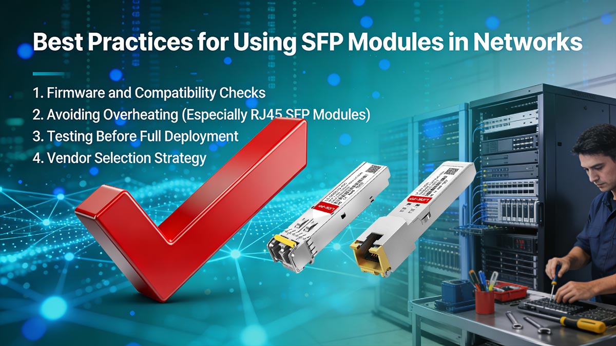
1. Firmware and Compatibility Checks
Before deploying any SFP module, it is essential to verify both hardware and firmware compatibility.
Key steps include:
Confirm switch/router firmware supports the specific SFP module type
Check vendor compatibility lists or transceiver approval matrices
Ensure the device recognizes third-party or compatible optics (if used)
Update firmware when necessary to enable newer transceiver support
Many deployment issues labeled as “SFP failure” are actually caused by outdated firmware or strict vendor validation rules, not hardware defects.
2. Avoiding Overheating (Especially RJ45 SFP Modules)
Thermal management is a critical but often overlooked factor in SFP deployment.
Important considerations:
RJ45 copper SFP modules generate significantly more heat than fiber modules
High-density switches can create thermal accumulation around adjacent ports
Poor airflow can reduce module performance and lifespan
Elevated temperatures may trigger link instability or automatic shutdowns
Best practices:
Avoid clustering high-power RJ45 SFP modules together
Ensure proper rack ventilation and airflow direction
Monitor module temperature using DOM (if supported)
Prefer fiber optics in high-density or high-speed environments when possible
3. Testing Before Full Deployment
Pre-deployment testing is a key step in preventing large-scale network failures.
Recommended testing process:
Validate link establishment in a controlled environment
Perform throughput testing under real traffic conditions
Check compatibility across both ends of the connection
Monitor optical power levels, temperature, and error rates
A short validation phase can prevent costly downtime in production networks, especially in cross-vendor deployments.
4. Vendor Selection Strategy
Choosing the right supplier is just as important as selecting the correct module specification.
Key evaluation criteria include:
Proven compatibility with major switch brands
Compliance with MSA standards (ensuring baseline interoperability)
Quality control and testing procedures
Availability of technical support and documentation
Consistency across product batches
A strong vendor strategy helps reduce risks associated with:
Firmware incompatibility
EEPROM mismatch issues
Unstable optical performance
In practice, enterprises often balance cost efficiency with compatibility reliability by selecting tested third-party compatible transceivers from reputable manufacturers.
By following these best practices, network engineers can significantly reduce deployment risks and ensure more predictable performance across SFP-based infrastructures. This completes the full framework of understanding, evaluating, and safely deploying SFP modules in modern networks.
🟡 Conclusion — Understanding the SFP Standard for Safe Deployment
The SFP Standard is one of the most widely used foundations in modern networking, enabling scalable, modular connectivity across enterprise switches, data centers, and telecom infrastructure. However, as this article has shown, the term “standard” should not be interpreted as universal plug-and-play compatibility.
Instead, SFP represents a structured hardware framework defined by the MSA, where true interoperability depends on a combination of technical specifications, vendor policies, and real-world deployment conditions.
1. Key Takeaways
To summarize the most important insights:
The SFP Standard defines physical form factor and basic electrical interface, not full compatibility
Real-world interoperability depends on vendor firmware, speed, and optical parameters
SFP, SFP+, and SFP28 share similar shapes but differ significantly in electrical performance and signaling
Many deployment issues come from ecosystem restrictions, not hardware failure
“Standard-compliant” does not always mean “works in every switch”
Core insight:
SFP is standardized in design, but conditional in operation.
2. Decision Framework for Safe SFP Deployment
When selecting or deploying SFP modules, a structured decision process helps avoid most compatibility issues:
Step 1: Identify port capability
Confirm whether the port supports SFP, SFP+, or SFP28
Check if multi-rate support (1G/10G/25G) is enabled
Step 2: Match optical requirements
Ensure correct fiber type (SMF vs MMF)
Match wavelength and transmission distance
Step 3: Verify vendor compatibility
Check switch or router compatibility list
Determine whether third-party optics are supported
Step 4: Validate speed configuration
Ensure both ends operate at the same data rate
Disable or enable auto-negotiation where required
3. Risk Reduction Checklist
Before deploying SFP modules in production, use this checklist:
✔ Confirm module is MSA-compliant
✔ Match speed (1G / 10G / 25G) with host port capability
✔ Verify fiber type and wavelength alignment
✔ Check vendor compatibility restrictions
✔ Ensure firmware supports the module type
✔ Test link stability before full deployment
✔ Monitor temperature and power usage in high-density environments
4. Final Insight: Building Reliable SFP Networks
In modern network design, reliability is not determined by the SFP standard alone, but by how well the entire system is aligned—hardware, firmware, and optical infrastructure working together.
Organizations that treat SFP selection as a strategic decision rather than a simple hardware swap consistently achieve:
Fewer network outages
Lower troubleshooting costs
Higher long-term scalability
More predictable performance across vendors
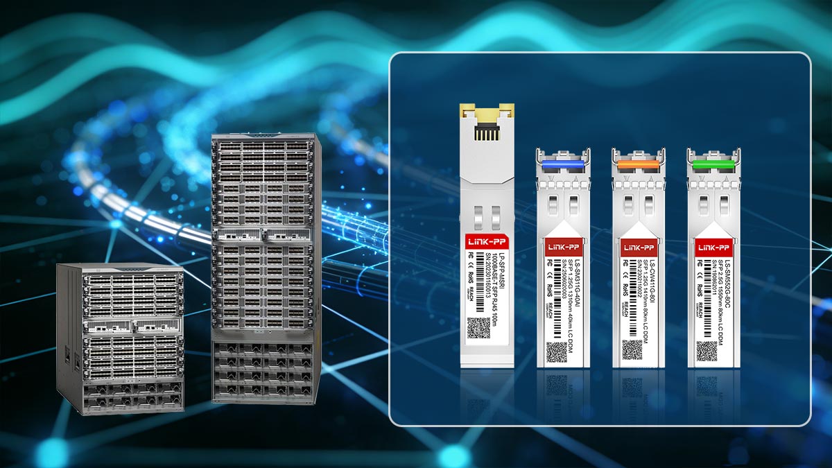
5. Reliable SFP Solutions
For network engineers and procurement teams seeking stable, tested, and production-ready SFP modules, choosing a reliable supplier is critical to minimizing compatibility risks.
👉 Explore high-quality, fully tested compatible transceivers at the
LINK-PP Official Store, designed to support enterprise-grade networking performance while maintaining strong cross-platform compatibility and cost efficiency.


