


In modern high-speed networks—from cloud data centers to fiber-optic telecom systems—signal integrity is everything. Even the smallest distortion in a digital signal can lead to data errors, reduced transmission distance, or complete link failure. This is where a Digital Communication Analyzer (DCA) becomes essential.
A Digital Communication Analyzer (DCA) is a precision test instrument used to analyze the quality of high-speed digital and optical signals, helping engineers visualize performance through eye diagrams, measure jitter, and verify compliance with industry standards. Unlike general-purpose oscilloscopes, DCAs are specifically designed for multi-gigabit communication systems, making them a critical tool in optical module development and validation.
As technologies such as 10G, 25G, 100G, and even 400G Ethernet continue to scale, ensuring clean and reliable signal transmission has become increasingly complex. Optical transceivers like SFP and QSFP modules must meet strict performance requirements—and DCA testing plays a central role in confirming that they do.
What You’ll Learn in This Article
By reading this guide, you will:
Understand what a Digital Communication Analyzer (DCA) is and how it works
Learn how DCAs are used in optical communication systems
Explore key measurements like eye diagrams, jitter, and extinction ratio
Discover why DCA testing directly impacts optical module performance and reliability
See how engineers use DCA results to ensure compliance with industry standards
Whether you are a network engineer, hardware designer, or a buyer evaluating optical modules, understanding the role of DCA will help you make better technical and purchasing decisions in high-speed communication environments.
✅ What Is a Digital Communication Analyzer (DCA)?
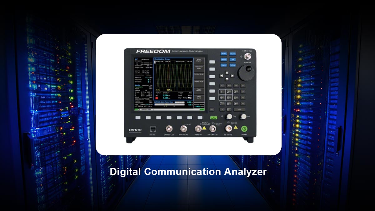
A Digital Communication Analyzer (DCA) is a high-precision test instrument used to measure, visualize, and analyze high-speed digital and optical signals. It is primarily used to generate eye diagrams, evaluate jitter, and verify signal integrity in multi-gigabit communication systems.
In simple terms, a DCA allows engineers to see how “clean” and reliable a digital signal is over time. Technically, it operates using advanced sampling techniques to reconstruct ultra-fast waveforms that cannot be captured directly in real time.
In modern networks—especially fiber-optic systems—a DCA plays a critical role in validating the performance of optical transceivers (such as SFP and QSFP modules) and ensuring compliance with industry standards.
✅ How a Digital Communication Analyzer Works
A DCA works differently from traditional oscilloscopes by using equivalent-time sampling, a method that reconstructs high-speed signals over multiple cycles.
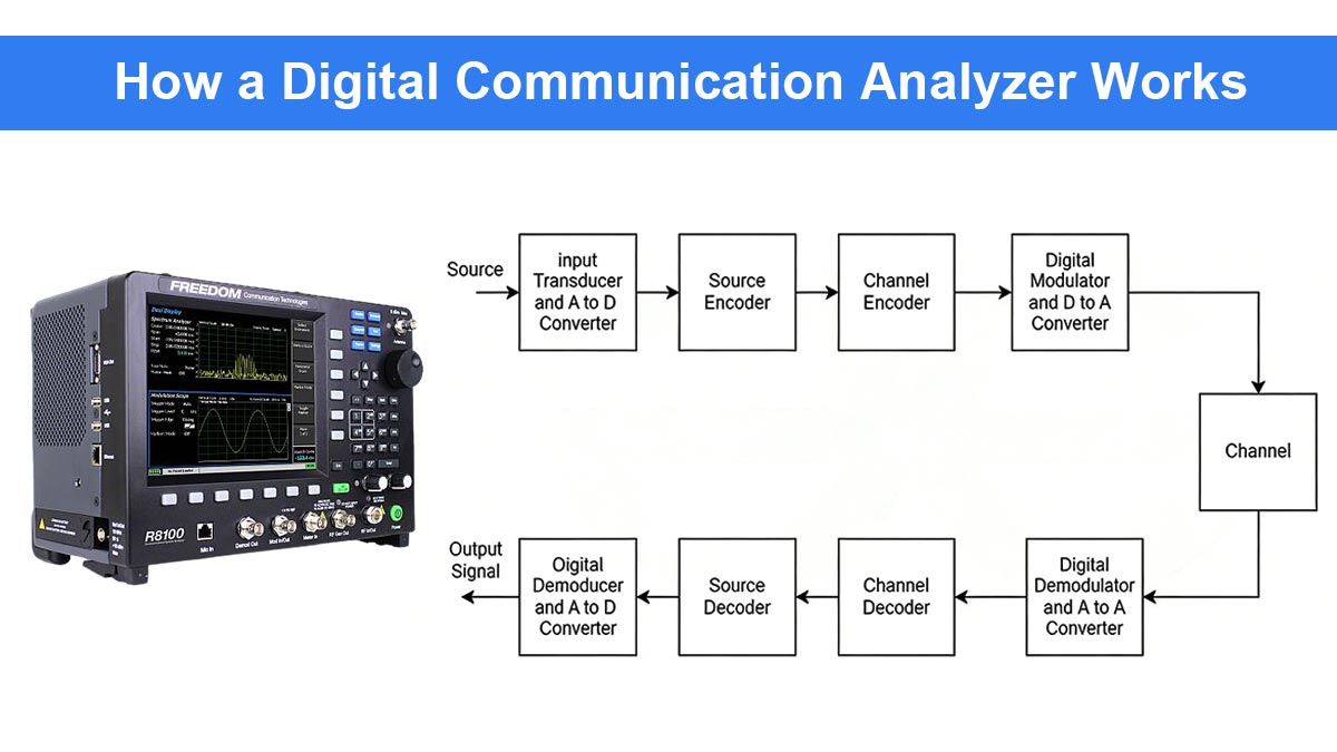
🔹 Equivalent-Time Sampling
Instead of capturing a full waveform in a single pass, the DCA:
Samples small portions of a repetitive signal
Reconstructs the waveform over time
Achieves extremely high effective bandwidth (well beyond real-time scopes)
🔹 Signal Reconstruction
By combining thousands (or millions) of sampled points:
The DCA builds a statistical representation of the signal
This enables accurate visualization of jitter, noise, and distortion
🔹 Electrical vs. Optical Inputs
Modern DCAs support both:
Electrical modules → for high-speed PCB and SerDes signals
Optical modules → for fiber communication testing
Optical sampling heads convert light signals into electrical signals for analysis, enabling direct testing of optical transmitters.
✅ Key Measurements Performed by a DCA
A DCA provides deep insight into signal integrity through several critical measurements:
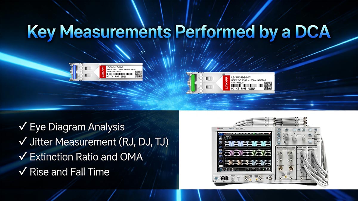
Eye Diagram Analysis
Overlays multiple bits to form a visual “eye”
Evaluates signal clarity and noise margin
Identifies distortion, interference, and timing issues
Jitter Measurement (RJ, DJ, TJ)
Random Jitter (RJ): noise-related, unpredictable
Deterministic Jitter (DJ): caused by system effects (e.g., crosstalk)
Total Jitter (TJ): combined impact
Excessive jitter can lead to bit errors and link instability
Extinction Ratio and OMA
Extinction Ratio (ER): difference between logical “1” and “0” optical power
Optical Modulation Amplitude (OMA): effective signal strength
These directly affect receiver sensitivity and transmission distance
Rise and Fall Time
Measures how quickly signals transition between states
Slow transitions → increased inter-symbol interference (ISI)
✅ Why Eye Diagrams Matter in Optical Communication
Eye diagrams are one of the most important outputs of a DCA because they provide a visual summary of signal integrity.
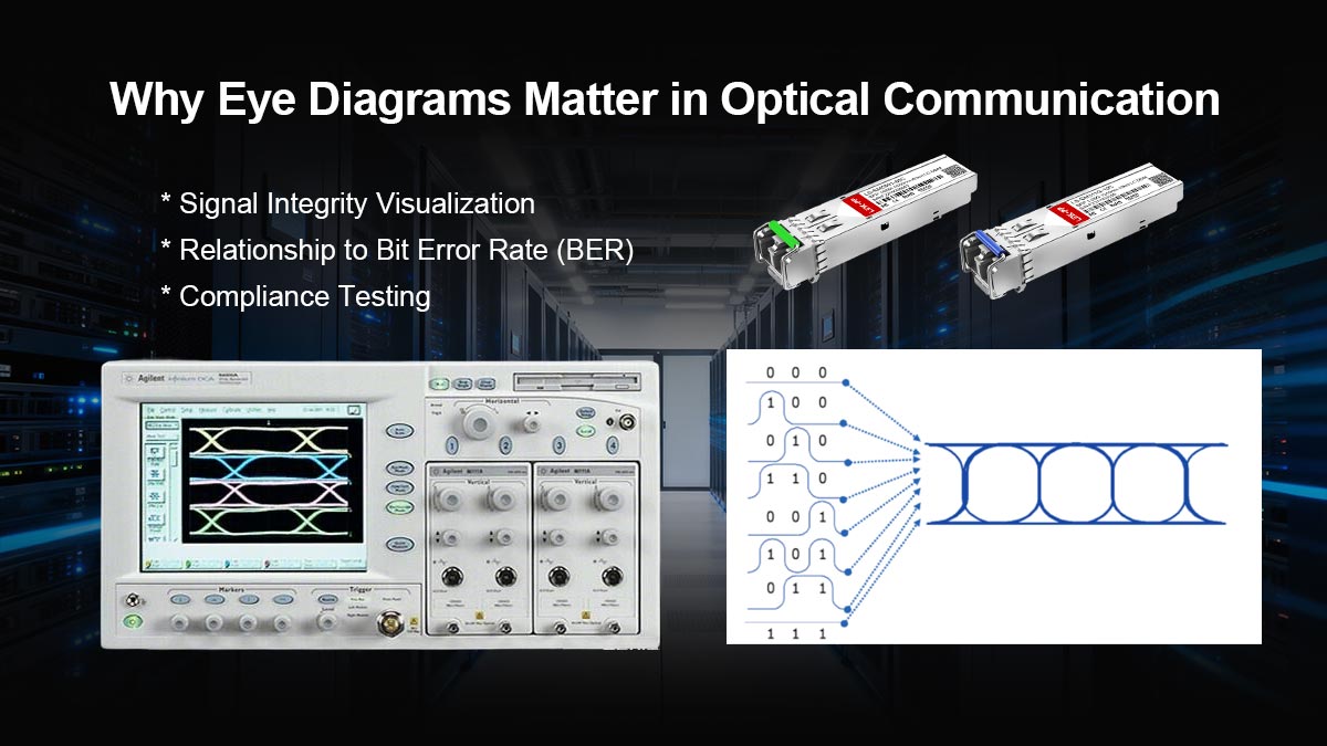
Signal Integrity Visualization
A “wide open” eye indicates:
Low noise
Stable timing
Strong signal quality
A “closed” eye suggests:
Distortion
Jitter
Potential data errors
Relationship to Bit Error Rate (BER)
A cleaner eye → lower probability of bit errors
A degraded eye → higher BER
Eye diagrams allow engineers to predict system reliability without long BER tests
Compliance Testing
Standards defined by organizations like IEEE specify eye masks.
Signals must not cross forbidden regions
DCA verifies compliance with these masks
✅ Role of DCA in Optical Module Testing (SFP, QSFP, etc.)
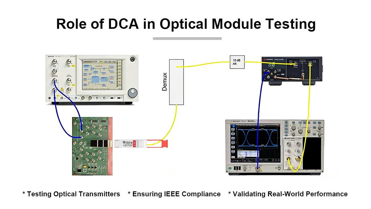
The DCA is a core tool in optical transceiver validation, especially for modules such as:
Testing Optical Transmitters
DCA measures:
Optical waveform quality
Modulation characteristics
Timing performance
Ensuring IEEE Compliance
Optical modules must comply with standards like:
IEEE 802.3 (Ethernet)
DCA verifies:
Eye mask compliance
Jitter limits
Signal amplitude
Validating Real-World Performance
Before deployment, DCA testing ensures:
Compatibility with switches and routers
Stable long-distance transmission
Low error rates in production environments
✅ How DCA Impacts Optical Module Performance
The results obtained from a DCA directly influence how an optical module performs in real networks.
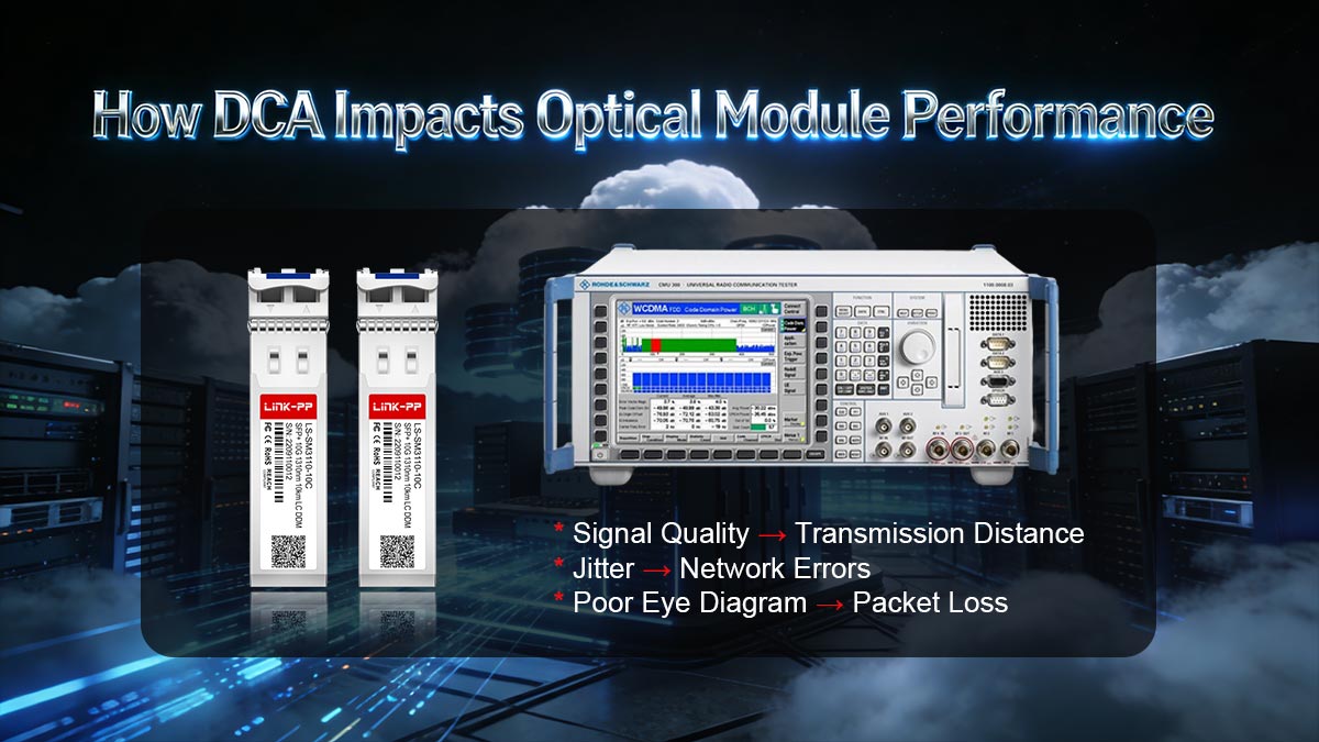
Signal Quality → Transmission Distance
Strong, clean signals travel farther
Poor signal quality reduces effective link distance
Jitter → Network Errors
High jitter causes sampling errors at the receiver
Leads to retransmissions and latency issues
Poor Eye Diagram → Packet Loss
Closed eye → higher BER
Results in dropped packets and unstable links
For buyers and engineers, this means: DCA-tested modules are more reliable and predictable in deployment
✅ DCA vs. Oscilloscope vs. BERT: What’s the Difference?
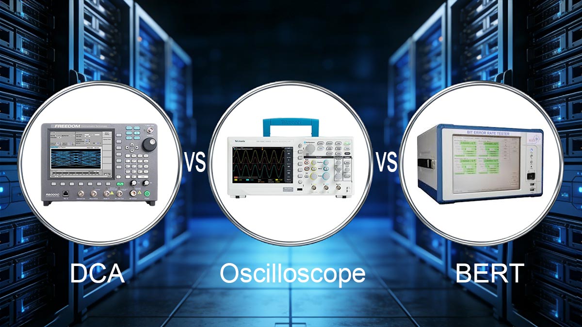
Tool | Primary Function | Best Use Case |
|---|---|---|
DCA | Signal integrity analysis | Eye diagrams, optical testing |
Oscilloscope | General waveform capture | Circuit debugging |
BERT | Bit error measurement | BER validation |
When to Use Each
Use DCA → for optical signal quality and compliance
Use oscilloscope → for real-time debugging
Use BERT → for long-duration error testing
These tools are complementary, not interchangeable.
✅ Industry Standards and DCA Compliance
DCA measurements are essential for verifying compliance with key industry standards:
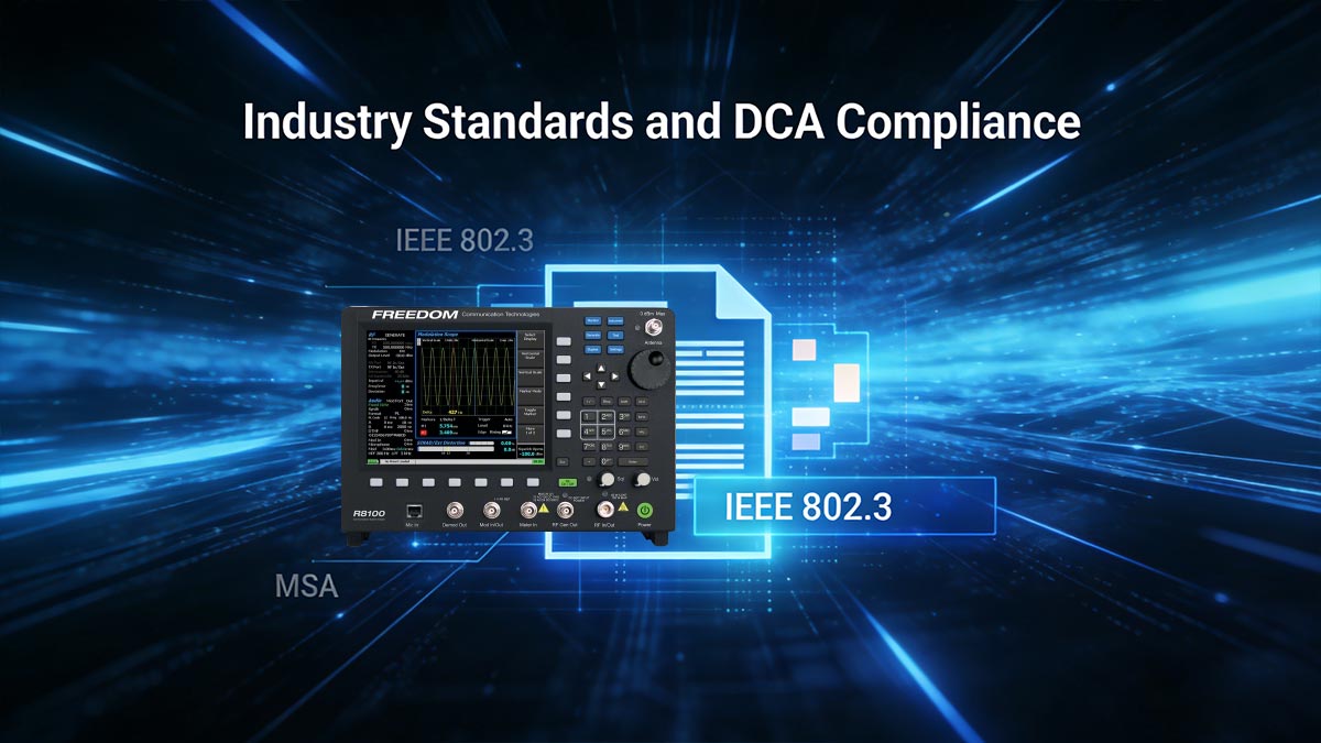
IEEE 802.3
Defines:
Ethernet physical layer requirements
Optical signal specifications
MSA (Multi-Source Agreement)
Defines:
Mechanical and electrical compatibility
Optical performance expectations
Eye Mask Testing
Standardized pass/fail criteria
Ensures interoperability across vendors
Without DCA validation, modules may fail interoperability in multi-vendor networks.
✅ Practical Use Case: Testing an SFP Module with a DCA
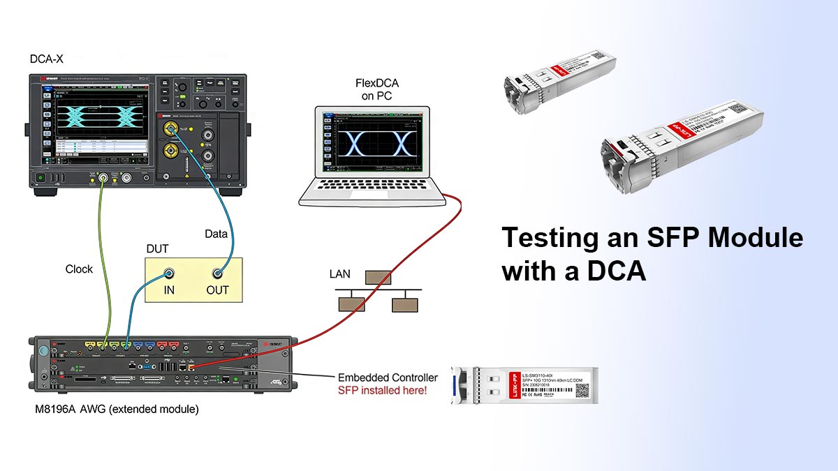
Step-by-Step Process
Connect the SFP module to a test setup
Feed a known data pattern into the transmitter
Use an optical sampling head on the DCA
Capture and generate the eye diagram
Measure jitter, ER, OMA, rise/fall time
Compare results with standard limits
What Engineers Look For
Eye opening (signal clarity)
Jitter within acceptable limits
Proper extinction ratio
Clean transitions
Common Failure Indicators
Closed or distorted eye diagram
Excessive jitter
Low OMA or extinction ratio
Mask violations
✅ FAQ About Digital Communication Analyzer (DCA)
1. What does a DCA measure?
A DCA measures signal integrity parameters such as eye diagrams, jitter, extinction ratio, optical modulation amplitude, and timing characteristics.
2. Is DCA the same as an oscilloscope?
No. A DCA uses equivalent-time sampling for high-speed analysis, while an oscilloscope captures signals in real time for general debugging.
3. Why is eye diagram testing important?
It visually represents signal quality and helps predict bit error rate (BER) and overall link reliability.
4. Can DCA measure BER?
Not directly. A DCA estimates signal quality, while BER is measured using a Bit Error Rate Tester (BERT).
✅ Conclusion: Why DCA Is Critical in Optical Networks
A Digital Communication Analyzer (DCA) is an essential tool for ensuring the performance, reliability, and compliance of high-speed optical communication systems. By providing deep insight into signal integrity—through eye diagrams, jitter analysis, and optical measurements—it enables engineers to detect issues early and optimize system performance.
For optical modules such as SFP and QSFP, DCA testing is not optional—it is a fundamental requirement for meeting industry standards and ensuring interoperability in real-world deployments.
When selecting optical transceivers, choosing products that have undergone rigorous DCA validation ensures:
Stable long-distance transmission
Low error rates
Reliable network performance
👉 Explore high-quality, DCA-tested optical modules at LINK-PP Official Store to ensure your network operates with maximum efficiency and confidence.


