

An SFP link is the active network connection established through an SFP or SFP+ transceiver between devices such as switches, routers, servers, or optical network equipment. If the link fails to come up, the cause is usually not the TCP/IP layer itself, but a lower-layer issue involving optical compatibility, fiber polarity, speed negotiation, wavelength mismatch, or physical signal integrity. In enterprise and data center environments, stable SFP links are critical because even small optical-layer problems can lead to packet loss, CRC errors, link flapping, or complete service interruption.
As 10G, 25G, and higher-speed Ethernet deployments continue to expand across cloud infrastructure, SMB networks, industrial Ethernet, and AI data centers, SFP-based connectivity remains one of the most widely used physical-layer interconnect technologies. Whether using multimode fiber, single-mode fiber, DAC cables, or RJ45 copper transceivers, the reliability of the SFP link directly affects bandwidth stability, latency consistency, and overall network uptime.
One reason the keyword “SFP Link” has strong search demand is that users are often trying to solve very practical problems:
Why is the SFP link light off?
Why does the SFP port show “down” even when the cable is connected?
Can different-brand SFP modules work together?
Why does the link keep flapping intermittently?
Should I use fiber, DAC, or RJ45 SFP modules?
These are not just beginner questions. Even experienced network engineers frequently encounter interoperability issues caused by vendor-coded optics, Digital Optical Monitoring (DOM) inconsistencies, Forward Error Correction (FEC) mismatches, or incorrect optical power budgets.
This guide explains the meaning of an SFP link, how SFP links are established, the most common reasons links fail, and how to troubleshoot them systematically in real production environments. It also compares fiber, DAC, and copper-based SFP deployments to help network designers choose the most reliable solution for different application scenarios.
By reading this article, you will learn:
What an SFP link is at the physical and protocol layers
Why SFP links fail even when hardware appears connected
How to troubleshoot SFP link issues step by step
How compatibility and vendor coding affect interoperability
How to reduce link flapping, packet loss, and CRC/FCS errors
Best practices for selecting stable SFP transceivers for enterprise networks
For readers deploying optical infrastructure at scale, this article also references industry standards such as IEEE 802.3 and practical field experience from enterprise switching, fiber uplinks, and data center interconnect deployments.
🟠 What Is an SFP Link?
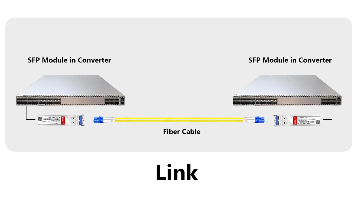
An SFP link is the active communication path created when two network devices establish a successful physical-layer connection through SFP or SFP+ transceivers. The link becomes operational only when both sides agree on parameters such as speed, wavelength, encoding method, and signal integrity. In Ethernet networks, the SFP link acts as the physical transport layer that carries data between switches, routers, servers, storage systems, or optical transmission equipment.
Understanding the Meaning of an SFP Link
SFP stands for Small Form-factor Pluggable, a hot-swappable transceiver standard widely used in enterprise networking and data centers. The SFP module itself is not the “link.” Instead, it enables the connection by converting electrical signals into optical or copper transmission signals.
In simple terms:
The SFP module is the hardware, while the SFP link is the live connection created through it.
A typical SFP link includes:
Two compatible SFP/SFP+ modules
Fiber, DAC, or copper cabling
Matching port configurations
Stable signal synchronization
If any of these fail, the link may stay down or become unstable.
How an SFP Link Is Established
When an SFP module is inserted, the switch or router reads the module information and checks compatibility. After the cable is connected, both devices begin physical-layer negotiation, including signal detection, speed matching, and synchronization.
The link LED turns on only after the connection becomes stable.
Step | Process |
|---|---|
1 | Detect SFP module |
2 | Verify compatibility |
3 | Connect cable/fiber |
4 | Synchronize signals |
5 | Establish link |
Common Types of SFP Links
Fiber Optic SFP Links
Used for long-distance and high-speed transmission through multimode or single-mode fiber. Common standards include 10GBASE-SR and 10GBASE-LR.
Fiber links provide:
Longer transmission distance
Better EMI resistance
Lower latency
Higher bandwidth scalability
DAC SFP Links
Direct Attach Copper (DAC) cables are commonly used for short-distance server-to-switch connections inside racks.
Common deployment scenarios:
Top-of-rack (ToR) switching
Server-to-switch interconnects
Short-distance 10G/25G links
RJ45 Copper SFP Links
These modules allow Ethernet over Cat5e/Cat6 copper cables, but they often generate more heat and compatibility issues than fiber optics.
These links are attractive because they:
Reuse existing copper infrastructure
Simplify SMB deployments
Reduce fiber installation costs
SFP Link vs. Ethernet Link: What Is the Difference?
An Ethernet link describes the logical network connection between two devices.
An SFP link specifically refers to the physical transceiver-based transport mechanism that carries the Ethernet frames.
Think of it this way:
Term | Meaning |
|---|---|
Ethernet Link | Logical network communication |
SFP Link | Physical optical/electrical transport path |
Without a stable SFP link, the Ethernet layer cannot reliably transmit packets.
What Usually Causes an SFP Link Failure?
Most SFP link problems are physical-layer related.
Common causes include:
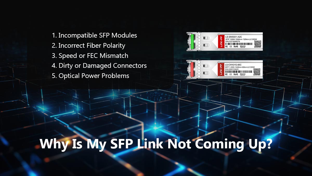
Incompatible SFP modules
Incorrect fiber polarity
Speed or FEC mismatch
Dirty LC connectors
Unsupported vendor coding
Optical power loss
Even if the module is inserted correctly, the link may still fail if these conditions are not met.
Key Takeaways
An SFP link is the physical connection created through SFP transceivers.
The link depends on compatibility, signal quality, and correct negotiation.
Fiber, DAC, and RJ45 SFP links have different deployment scenarios.
Most SFP link failures originate from physical-layer issues rather than software problems.
🟠 Why Is My SFP Link Not Coming Up?
If an SFP link is not coming up, the problem is usually caused by physical-layer issues rather than IP or routing configuration. The most common causes include incompatible SFP modules, incorrect fiber polarity, speed mismatches, unsupported FEC settings, dirty connectors, or insufficient optical signal strength. In enterprise networks, verifying compatibility and signal integrity is usually the fastest way to restore the link.
The Most Common Reasons an SFP Link Stays Down
When the SFP port LED remains off or the interface shows “Link Down,” start with these high-probability causes first.
Problem | Typical Result |
|---|---|
Unsupported SFP module | Port disabled |
Wrong fiber TX/RX polarity | No optical signal |
Speed mismatch | Link failure |
Dirty LC connectors | CRC/FCS errors |
FEC mismatch | Link flapping |
Wrong wavelength pairing | No synchronization |
Damaged fiber cable | Intermittent connection |
In real deployments, compatibility problems and fiber polarity mistakes are among the most common issues.
1. Incompatible SFP Modules
Many switches and routers check the EEPROM information inside the SFP module. If the module is not vendor-approved or correctly coded, the port may refuse to establish a link.
Typical examples include:
Cisco-coded optics in non-Cisco switches
Unsupported RJ45 SFP modules
Mixing 1G and 10G optics incorrectly
Some devices allow third-party optics, while others enforce strict compatibility policies.
Micro-definition: EEPROM is the memory chip inside an SFP module that stores vendor and capability information.
2. Incorrect Fiber Polarity
Fiber links require proper TX-to-RX alignment.
If transmit and receive fibers are reversed:
Optical power is not detected
The link remains down
No synchronization occurs
This is one of the most common installation mistakes in LC duplex fiber deployments.
3. Speed or FEC Mismatch
Both devices must support the same link speed and Forward Error Correction (FEC) mode.
Examples:
10G port connected to 1G optic
One side using RS-FEC while the other side disables FEC
Auto-negotiation inconsistencies
Higher-speed Ethernet links such as 25G and 100G are especially sensitive to FEC configuration.
4. Dirty or Damaged Connectors
Even microscopic dust on LC connectors can significantly weaken optical signals.
Common symptoms include:
Link instability
CRC/FCS errors
Intermittent packet loss
Random link flapping
Best practice:
Always clean fiber connectors before insertion
Use fiber inspection tools when possible
5. Optical Power Problems
Every fiber link has an optical power budget.
If signal loss becomes too high because of:
Long transmission distance
Excessive patch panels
Poor splicing
Bent fiber cables
…the receiver may fail to detect a stable signal.
This is especially common in long-range single-mode deployments.
Quick Troubleshooting Checklist
Before replacing hardware, verify these items:
Confirm both SFP modules are compatible
Check TX/RX fiber polarity
Match link speed on both devices
Verify FEC settings
Clean LC connectors
Inspect fiber cable condition
Review DOM optical power readings
Test with known-good optics
Key Takeaways
Most SFP link failures are physical-layer problems.
Compatibility, polarity, and signal quality are the most common root causes.
Dirty fiber connectors can cause major instability even when the hardware appears connected.
Systematic troubleshooting is faster than randomly replacing transceivers.
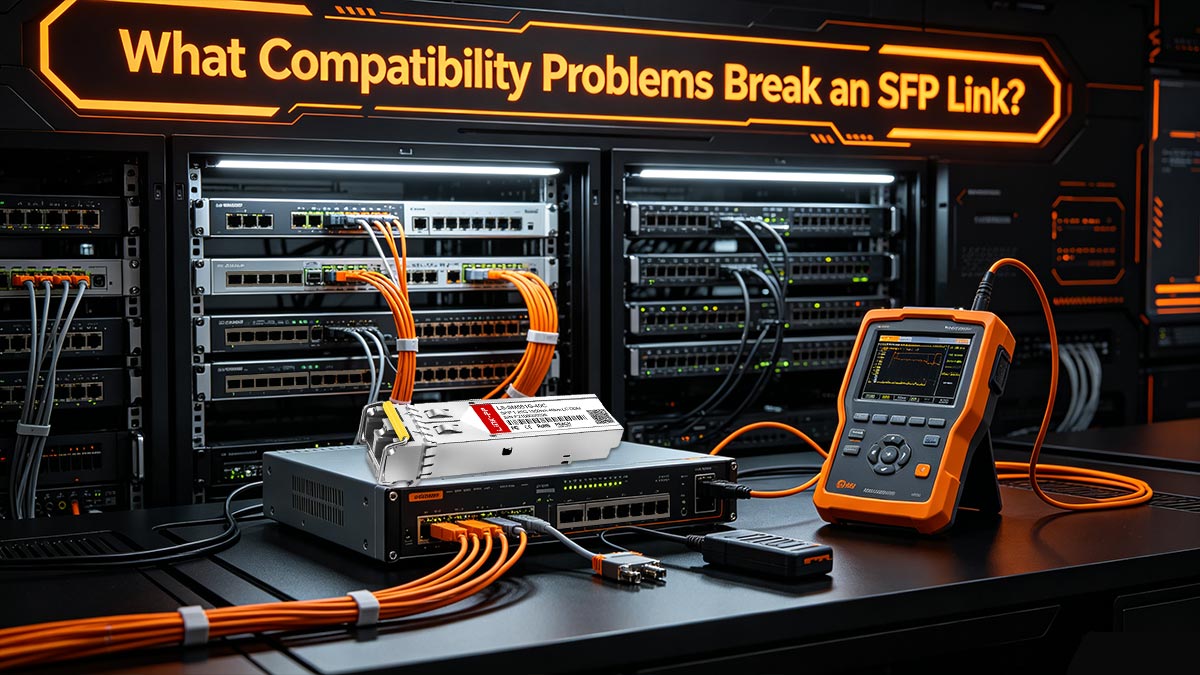
🟠 What Compatibility Problems Break an SFP Link?
SFP compatibility problems occur when the transceiver, switch, cable, or port settings cannot operate together correctly. The most common issues include vendor-coded optics, speed mismatches, unsupported wavelengths, FEC incompatibility, and differences between SFP and SFP+ standards. In production networks, compatibility problems are one of the leading causes of SFP links staying down or flapping intermittently.
Why SFP Compatibility Matters
Many users assume all SFP modules follow the same standard and should work universally. In reality, modern switches and routers often validate:
Vendor coding
EEPROM information
Supported Ethernet standards
Optical parameters
Power requirements
If the device rejects any of these conditions, the port may disable the link entirely.
Micro-definition: Vendor coding refers to the identification data programmed into the SFP module EEPROM to match specific switch manufacturers.
1. Vendor-Coded SFP Modules
One of the most common causes of SFP link failure is vendor lock-in.
Some network brands only allow approved optics. If the EEPROM coding does not match the vendor policy:
The port may remain disabled
Warning messages may appear
DOM monitoring may fail
The link may become unstable
Common environments affected:
Cisco
HPE
Juniper
Arista
Ubiquiti
Intel NICs
This is why many Reddit users search for:
“Intel coded transceiver”
“Third-party SFP not recognized”
2. SFP vs. SFP+ Speed Mismatch
SFP and SFP+ modules are physically similar, but they support different speeds.
Module Type | Typical Speed |
|---|---|
SFP | 1G |
SFP+ | 10G |
Common mistakes include:
Installing a 1G optic into a 10G-only port
Connecting 10G optics to devices locked at 1G
Mixing unsupported auto-negotiation settings
Some ports support backward compatibility, while others do not.
3. Wavelength and Fiber Type Mismatch
Fiber links require matching optical specifications.
Examples:
850nm SR optics must pair with 850nm SR optics
1310nm LR optics must connect to compatible LR modules
Single-mode and multimode fiber cannot always be mixed safely
Incorrect combinations often cause:
No optical synchronization
Weak signal detection
Link instability
4. Unsupported FEC Settings
Higher-speed Ethernet links increasingly depend on Forward Error Correction (FEC).
If one side enables RS-FEC while the other side disables FEC:
The link may fail completely
Packet errors may increase
Intermittent flapping may occur
This issue is especially common in:
25G Ethernet
100G uplinks
DAC deployments
Micro-definition: FEC (Forward Error Correction) is a physical-layer error recovery mechanism used in high-speed Ethernet transmission.
5. RJ45 Copper SFP Compatibility Problems
RJ45 SFP modules create more compatibility challenges than optical modules because they contain integrated PHY chips and consume more power.
Common problems include:
Excessive heat
Unsupported power draw
PHY negotiation failures
Limited port support
Some switches only support specific RJ45 transceiver models even when standard SFP optics work normally.
Compatibility Troubleshooting Checklist
Before replacing hardware, verify:
The switch officially supports the SFP module
Both sides use the same speed standard
Wavelengths match correctly
Fiber type matches the optic specification
FEC settings align
Firmware is updated
RJ45 SFP power requirements are supported
Key Takeaways
SFP compatibility problems are one of the most common causes of link failure.
Vendor coding, speed mismatches, and FEC settings frequently break links.
RJ45 SFP modules often create additional compatibility risks.
Matching optics, fiber type, and Ethernet standards is essential for stable operation.
🟠 Troubleshoot SFP Link Issues Step by Step
The fastest way to troubleshoot an SFP link issue is to isolate the problem layer by layer. Start by checking physical connectivity, then verify module compatibility, optical signal quality, speed configuration, and FEC settings. In enterprise environments, most SFP link failures can be identified within minutes using a structured troubleshooting process instead of randomly replacing hardware.
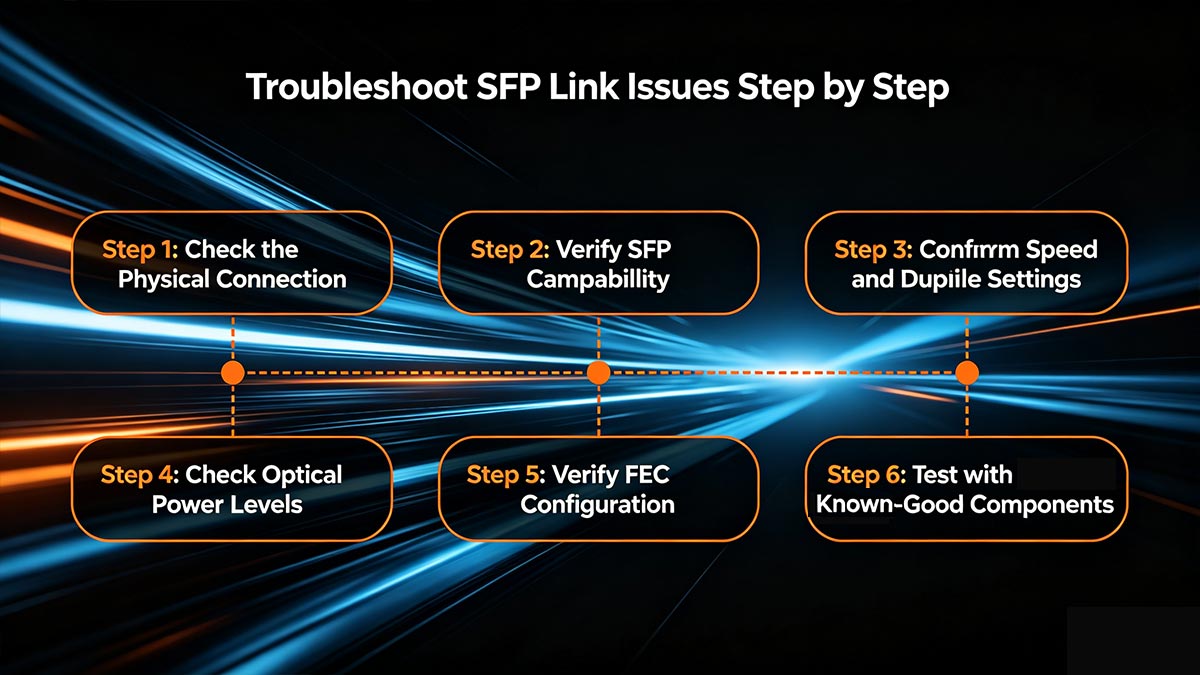
Step 1: Check the Physical Connection
Start with the simplest causes first.
Verify:
The SFP module is fully inserted
The fiber or DAC cable is securely connected
The port LED shows activity
The cable is not bent or damaged
For fiber links:
Confirm TX connects to RX
Check LC connector cleanliness
Dirty fiber connectors are one of the most overlooked causes of CRC/FCS errors and unstable links.
Step 2: Verify SFP Compatibility
Check whether the switch or router supports the installed transceiver.
Common compatibility problems include:
Unsupported vendor coding
Incorrect EEPROM information
Unsupported RJ45 SFP modules
Mixing 1G and 10G optics
A quick test is to replace the module with a known-compatible optic.
Micro-definition: EEPROM is the identification memory inside an SFP module that stores vendor and capability data.
Step 3: Confirm Speed and Duplex Settings
Both sides of the link must use compatible Ethernet settings.
Verify:
Link speed matches
Auto-negotiation settings align
Port mode is configured correctly
Typical examples:
1G optic inserted into a 10G-only port
Forced speed mismatch
Incorrect breakout configuration
Step 4: Check Optical Power Levels
Modern transceivers support DOM (Digital Optical Monitoring), allowing engineers to view:
TX optical power
RX optical power
Temperature
Voltage
If RX power is too low:
Fiber attenuation may be excessive
Connectors may be dirty
The cable may be damaged
If RX power is too high:
Receiver overload can occur on short-distance single-mode links
Step 5: Verify FEC Configuration
Higher-speed Ethernet links such as 25G and 100G often require matching FEC settings.
If one side uses RS-FEC and the other side disables FEC:
The link may stay down
Packet errors may increase
Link flapping may occur
This is especially common with DAC and high-speed optical links.
Step 6: Test with Known-Good Components
If the problem remains unresolved, isolate the fault by swapping components individually.
Test:
Another SFP module
Another fiber cable
Another switch port
Another device
This method quickly identifies whether the issue is caused by:
The optic
The cable
The switch hardware
The configuration
Fast SFP Troubleshooting Checklist
Check Item | Purpose |
|---|---|
Verify module insertion | Confirm physical connection |
Check fiber polarity | Ensure TX/RX alignment |
Clean LC connectors | Remove optical contamination |
Confirm compatibility | Avoid vendor lock issues |
Match speed/FEC settings | Prevent negotiation failure |
Review DOM readings | Validate signal quality |
Swap known-good optics | Isolate hardware faults |
Key Takeaways
Most SFP link problems can be solved through structured physical-layer troubleshooting.
Compatibility, fiber polarity, and optical signal quality are the most critical checks.
DOM readings provide valuable real-time diagnostic information.
Replacing components randomly is slower than systematic isolation testing.
🟠 How Do You Prevent Link Flapping and Intermittent Errors?
To prevent SFP link flapping and intermittent network errors, focus on physical-layer stability first. The most effective methods include using compatible transceivers, maintaining clean fiber connections, matching FEC and speed settings, monitoring DOM optical power levels, and avoiding poor-quality cables or overheated RJ45 SFP modules. In most enterprise networks, unstable SFP links are caused by signal integrity problems rather than switching software itself.

What Is Link Flapping?
Link flapping occurs when the SFP connection repeatedly changes between:
Link Up
Link Down
This instability can happen within seconds or intermittently throughout the day.
Common symptoms include:
Random disconnects
Packet loss
CRC/FCS errors
Slow network performance
STP recalculation events
Storage or VM migration failures
In data centers, even short link interruptions can affect application stability and latency-sensitive workloads.
1. Use High-Quality Compatible SFP Modules
Low-quality or incorrectly coded optics are one of the biggest causes of unstable links.
Best practices:
Use vendor-compatible transceivers
Avoid uncertified low-cost optics
Match the correct Ethernet standard
Verify switch compatibility lists
This is especially important for:
10G/25G uplinks
Enterprise switches
Intel NIC environments
RJ45 copper SFP modules
2. Keep Fiber Connectors Clean
Optical contamination is a major cause of intermittent signal loss.
Even microscopic dust can cause:
Increased attenuation
Signal reflection
CRC/FCS errors
Link instability
Best practices:
Clean LC connectors before installation
Use dust caps when ports are unused
Avoid touching fiber end faces directly
Micro-definition: Attenuation is the gradual loss of optical signal strength during transmission.
3. Monitor Optical Power with DOM
DOM (Digital Optical Monitoring) helps detect signal degradation before complete failure occurs.
Warning signs:
RX power near minimum threshold
Sudden optical fluctuations
Abnormally high module temperature
Proactive DOM monitoring is now standard practice in enterprise and AI data center environments.
4. Match Speed and FEC Settings
Higher-speed Ethernet links require consistent physical-layer configuration.
Common causes of instability:
Speed mismatch
Unsupported auto-negotiation
RS-FEC mismatch
Incorrect breakout configuration
25G, 40G, and 100G Ethernet links are particularly sensitive to FEC inconsistencies.
5. Avoid Poor Cable Management
Physical cable stress can damage optical performance over time.
Avoid:
Tight fiber bends
Excessive pulling force
Overheated cable bundles
Low-quality DAC assemblies
For long-term stability:
Follow minimum bend-radius specifications
Use proper cable labeling and routing
Separate power and fiber pathways when possible
6. Watch for RJ45 SFP Heat Problems
RJ45 copper SFP modules consume more power than optical transceivers.
Excessive heat can cause:
PHY instability
Link resets
Packet corruption
Random disconnects
Best practices:
Ensure proper switch airflow
Avoid fully populating adjacent high-heat ports
Use optical links for sustained high-bandwidth deployments when possible
Preventive Maintenance Checklist
Best Practice | Benefit |
|---|---|
Use compatible optics | Prevent negotiation failure |
Clean LC connectors | Reduce optical loss |
Monitor DOM values | Detect early degradation |
Match FEC settings | Improve high-speed stability |
Use quality cables | Reduce intermittent faults |
Control transceiver heat | Prevent random resets |
Key Takeaways
Link flapping is usually caused by physical-layer instability.
Dirty connectors, poor optics, and FEC mismatches are common root causes.
DOM monitoring helps identify problems before complete link failure occurs.
Proper cable management and thermal control improve long-term SFP reliability.
🟠 FAQ: Common SFP Link Questions
Q1: Can Any SFP Module Work in Any Switch?
No. Although SFP modules follow industry standards, many switches still enforce vendor compatibility checks through EEPROM coding.
Some switches support third-party optics, while others may:
Disable unsupported modules
Show compatibility warnings
Limit DOM functionality
Always verify the switch compatibility list before deployment.
Q2: Why Is My SFP Link Light Off?
An SFP link LED usually stays off because:
The module is unsupported
Fiber polarity is reversed
Optical signal is missing
Speed settings do not match
The cable or connector is damaged
Physical-layer problems are far more common than software issues.
Q3: Can I Mix Different SFP Brands?
Yes, in many cases. Two different-brand SFP modules can work together if:
Speeds match
Wavelengths match
Ethernet standards match
The switches allow third-party optics
However, vendor compatibility restrictions can still create problems.
Q4: What Is the Difference Between SFP and SFP+?
Type | Typical Speed |
|---|---|
SFP | 1GbE |
SFP+ | 10GbE |
SFP+ supports higher bandwidth and stricter signal requirements. Although the form factors are similar, not all ports support backward compatibility.
Q5: Why Does My SFP Link Keep Flapping?
Common causes include:
Dirty fiber connectors
Weak optical power
FEC mismatch
Poor-quality DAC cables
Overheated RJ45 SFP modules
Unstable physical connections
Link flapping usually indicates signal instability at the physical layer.
Q6: How Far Can an SFP Link Reach?
The maximum distance depends on:
Fiber type
Optical wavelength
Typical examples:
Standard | Fiber Type | Distance |
|---|---|---|
10GBASE-SR | Multimode | Up to 300m |
10GBASE-LR | Single-mode | Up to 10km |
Longer-distance optics are also available for metro and telecom networks.
Q7: Are RJ45 SFP Modules Reliable?
RJ45 SFP modules work well for short-distance copper deployments, especially in SMB environments. However, compared with optical transceivers, they typically:
Generate more heat
Consume more power
Have stricter compatibility requirements
For high-density or long-term high-bandwidth environments, fiber optics are usually more stable.
Q8: What Is DOM in an SFP Module?
DOM stands for Digital Optical Monitoring.
It allows network engineers to monitor:
TX optical power
RX optical power
Temperature
Voltage
DOM data is extremely useful for diagnosing intermittent SFP link problems before complete failure occurs.
🟠 Conclusion: The Fastest Way to Stabilize an SFP Link
The fastest way to stabilize an SFP link is to focus on the physical layer first. In most real-world deployments, unstable links are caused by compatibility mismatches, incorrect fiber connections, poor optical signal quality, or low-quality transceivers rather than higher-layer network protocols. A structured troubleshooting process combined with reliable optics is the most effective long-term solution.
What This Guide Shows About SFP Link Problems
Throughout this guide, one pattern appears repeatedly:
Most SFP link failures are preventable.
Whether the issue is:
Link down
Link flapping
CRC/FCS errors
Packet loss
Optical instability
RJ45 SFP overheating
…the root cause usually traces back to:
Physical-layer signal problems
Incompatible modules
Poor cable quality
Incorrect FEC or speed settings
Contaminated fiber connectors
This is why experienced network engineers troubleshoot from Layer 1 upward instead of starting with routing or application-level diagnostics.
The Most Important Best Practices
For long-term SFP link stability, prioritize these practices:
Best Practice | Why It Matters |
|---|---|
Use compatible transceivers | Prevent vendor and EEPROM conflicts |
Match speed and FEC settings | Avoid negotiation failures |
Clean fiber connectors | Reduce attenuation and CRC errors |
Monitor DOM values | Detect signal degradation early |
Use quality DAC/fiber cables | Improve signal integrity |
Control thermal conditions | Prevent overheating and link resets |
In modern 10G, 25G, and 100G Ethernet environments, physical-layer reliability directly affects overall network performance and uptime.
Choosing Reliable SFP Modules Matters
As enterprise networks, AI clusters, and cloud infrastructure continue moving toward higher bandwidth density, transceiver quality becomes increasingly important. Low-quality optics may appear functional during installation but often introduce intermittent instability under sustained workloads.
For this reason, many IT teams now standardize on:
Vendor-compatible optics
Strict optical testing procedures
DOM-based monitoring
Enterprise-grade transceiver suppliers
If you are planning a new deployment or replacing unstable modules, the LINK-PP Official Store provides a wide range of compatible SFP, SFP+, DAC, and optical networking solutions designed for enterprise, industrial, and data center environments.
Final Takeaway
An SFP link is more than a simple “link up” indicator. It is the foundation of stable Ethernet communication.
When compatibility, signal integrity, and optical quality are handled correctly:
Links become more stable
Packet loss decreases
CRC/FCS errors are reduced
Network uptime improves significantly
In high-speed modern networks, stable physical-layer connectivity is no longer optional — it is critical infrastructure.


